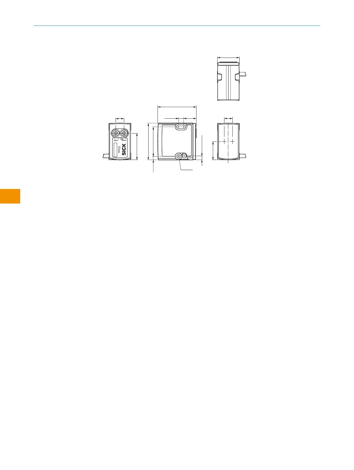
12.2 Dimensional drawing
21.5 (0.85)
8 (0.31)
26.1 (1.03)
18 (0.71)
36 (1.42)
3.5
(0.14)
29 (1.14)
12.4
(0.49)
5
(0.2)
8 (0.31)
Ø 3.5
(0.14)
37.7 (1.48)
3.8 (0.15)
1 2
3
4
5
6
8
7
Figure 22: Dimensional drawing
1
Potentiometer / LED Indicators (green)
2
Potentiometer / LED Indicators (orange)
3
Signal strength light bar during the teach process
CTA during run mode
4
Mounting hole M3 (Ø 3.1 mm)
5
Mounting hole M3 (Ø 3.1 mm)
6
Optical axis
7
Optical axis
8
Optical axis
12 TECHNICAL DATA
34
O P E R A T I N G I N S T R U C T I O N S | RAY10 8022198.1BXN / 2021-05-26 | SICK
Subject to change without notice
en