HINWEIS
Video der Inbetriebnahme:
18.2 Die Einsatzbedingungen prüfen:
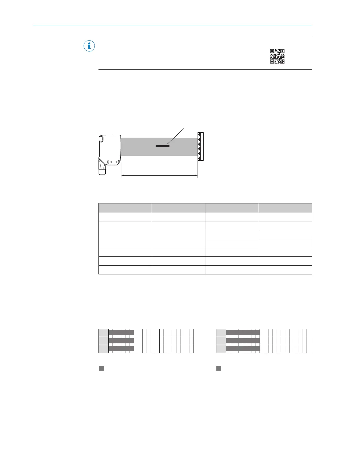
Schaltabstand
Den Abstand zwischen Sensor und Reflektor gemäß dem entsprechenden Diagramm
anpassen siehe Abbildung 19, Seite 30.
Abbildung 19: Schaltabstandsbereiche
Tabelle 13: Definition des Schaltabstands
1
2 3 4
RAY26P-xxxxx1 PL80A 0 ... 1,5 m ≥ 1 mm
A
RAY26P-xxxxx3 PL80A 0 ... 2 m ≥ 3 mm
B
0 ... 3 m ≥ 5 mm
B
0 ... 4,5 m ≥ 10 mm
B
RAY26P-xxxxx5 PL80A 0 ... 3 m ≥ 5 mm
A
RAY26P-xxxxx9 PL80A 0 ... 4,5 m ≥ 10 mm
A
RAY26P-xxxxxA PL80A 0 ... 4,5 m
C
3
Schaltabstand, auf Reflektor 2
4
Kleinstes detektierbares Objekt (MDO)
A
MDO ist fix
B
MDO ≥ 3 mm, ≥ 5 mm, ≥ 10 mm:
sind via IO-Link anwählbar
C
Werkseinstellung siehe Datenblatt
MDO ≥ 10 mm, ≥ 15 mm, ≥ 20 mm, ≥ 25 mm, ≥ 30 mm; wählbar über IO-Link
Tabelle 14: Schaltabstände auf Reflektoren
0
0
1,5
0
1,5
0
1,5
0
4
1 3
5
2
1
2
3
Schaltabstand
Abstand in m
Abbildung 20: RAY26P-xxxxx1
1
PL80A
2
PL40A
3
PL30A
0
0
2
0
2
0
2
0
4
1 3
5
2
1
2
3
Schaltabstand
Abstand in m
Abbildung 21: RAY26P-xxxxx3
1
PL80A
2
PL81
3
PL100
18 INBETRIEBNAHME
30
8022178.18JF 02.07.2020 | SICK
Subject to change without notice