NOTE
Video of commissioning:
7.2 Check the application conditions:
Sensing range
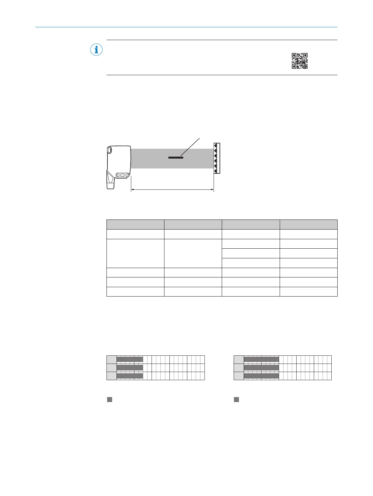
Reconcile the distance between the sensor and the reflector with the corresponding
diagram see figure 4, page 12.
Figure 4: sensing range areas
Table 5: Definition sensing range
1
2 3 4
RAY26P-xxxxx1 PL80A 0 ... 1.5 m ≥ 1 mm
A
RAY26P-xxxxx3 PL80A 0 ... 2 m ≥ 3 mm
B
0 ... 3 m ≥ 5 mm
B
0 ... 4.5 m ≥ 10 mm
B
RAY26P-xxxxx5 PL80A 0 ... 3 m ≥ 5 mm
A
RAY26P-xxxxx9 PL80A 0 ... 4.5 m ≥ 10 mm
A
RAY26P-xxxxxA PL80A 0 ... 4.5 m
C
3
Sensing range, on reflector 2
4
Minimum detectable object (MDO)
A
MDO is fix
B
MDO ≥ 3 mm, ≥ 5 mm, ≥ 10 mm:
can be selected via IO-Link
C
Factory setting see data sheet
MDO ≥ 10 mm, ≥ 15 mm, ≥ 20 mm, ≥ 25 mm, ≥ 30 mm; are selectable via IO-Link
Table 6: Sensing ranges on reflectors
0
0
1.5
0
1.5
0
1.5
0
Sensing range
4
(13.12)
Distance in m (feet)
1
(3.28)
3
(9.84)
5
(16.40)
2
(6.56)
1
2
3
Figure 5: RAY26P-xxxxx1
1
PL80A
2
PL40A
3
PL30A
0
0
2
0
2
0
2
0
Sensing range
4
(13.12)
Distance in m (feet)
1
(3.28)
3
(9.84)
5
(16.40)
2
(6.56)
1
2
3
Figure 6: RAY26P-xxxxx3
1
PL80A
2
PL81
3
PL100
7 COMMISSIONING
12
8022178.18JF 02.07.2020 | SICK
Subject to change without notice