RFU63x-131xx
Programming Application-specific programming with SICK AppStudio
6)
develop‐
ment environment.
You can find further information on the Internet at:
www.sick.com/SICK_AppStudio
1)
For example: Configuration, diagnosis, transponder access or display of the read results.
2)
Function blocks for various PLC manufacturers are available online at: www.sick.com/RFU63x.
3)
USB interface only for temporary use (service)
4)
Optional accessories.
5)
e.g. with SOPAS ET configuration software.
6)
Functions can be enabled with the SDK6U SD card. Available at: www.sick.com
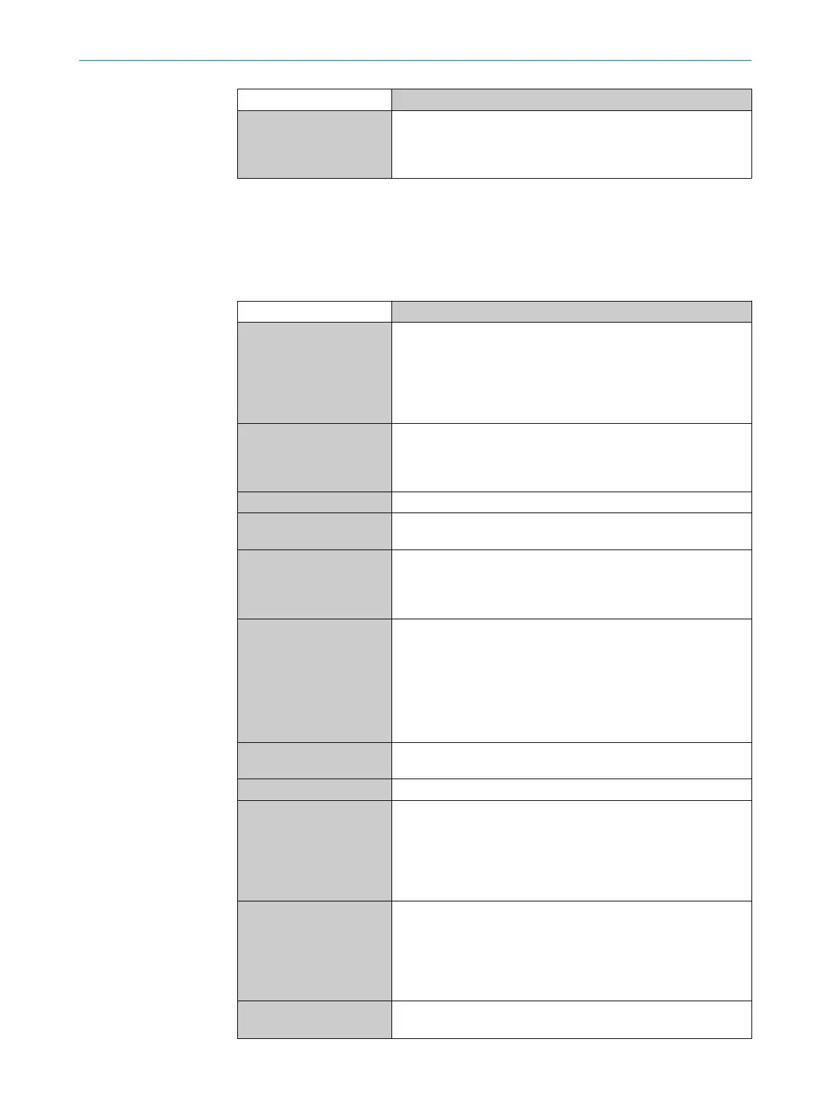
Table 25: Technical data for RFU63x-041xx: Interfaces
RFU63x-041xx
Ethernet Host for data output (read result)
Aux for service
1)
Protocol: TCP/IP
Data transmission rate 10/100 Mbit/s
Supported services and protocols (e.g. DHCP, HTTP/HTTPS ...), see
type-specific online data sheet at: www.sick.com/RFU63x
PROFINET
2)
PROFINET single port
PROFINET dual port: Via external CDF600-22xx
4)
fieldbus module
to PROFINET (2-port Ethernet) for data output (read result).
Data transmission rate 10/100 Mbit/s
EtherNet/IP™ Data transmission rate 10/100 Mbit/s
EtherCAT®
2)
Via external fieldbus module CDF600-0300
4)
(gateway mode) to
EtherCAT® (Ethernet) for data output (read result).
Serial RS-232, RS-422/485
Host for data output (read result)
Aux (only RS-232) for service
1)
Data transmission rate: 0.3 kBd ... 115.2 kBd, Aux: 57.6 kBd
CAN Host, data transmission rate: 20 kBit/s ... 1 MBit/s.
Bus length depends on data transmission rate and length of
cable. Typical: 250 m at 250 kBit/s and wire cross-section
≥ 0.34 mm
2
Protocols:
•
CSN (SICK CAN sensor network)
•
CANopen®
PROFIBUS
2)
Via external fieldbus module CDF600-21xx
4)
to PROFIBUS
(RS-485) for data output (read result)
USB
3)
Aux (USB 2.0) for service
1)
Digital switching inputs 2 x physical. Optional 2 x additional external logical inputs (soft‐
ware-controlled) via module CMC600
4)
in the CDB
4)
or CDM con‐
nection module
4)
V
in
= max. 30 V, I
in
= max. 5 mA
Opto-decoupled, reverse polarity protected, adjustable debounce
time
Digital switching outputs 2 x physical. Optional 2 x additional external logical outputs (soft‐
ware-controlled) via module CMC600
4)
in the CDB
4)
or CDM con‐
nection module
4)
V
out
= V
S
– 1.5 V, I
out
≤ 100 mA (typical)
Short-circuit protected, temperature protected, not electrically iso‐
lated from the supply voltage
Antenna Sending and receiving
4 x external
12 TECHNICAL DATA
90
O P E R A T I N G I N S T R U C T I O N S | RFU63x, RFU65x 8014335/ZTL9/2018-10-14 | SICK
Subject to change without notice
 Loading...
