5
Signal IN X
Posi‐
tion
Signal TiM3xx-01xxxx
(cable with flying
leads): wire color
TiM3xx-10xxxx (15-pin D-
Sub-HD male connector):
PIN
TiM3xx-11xxxx,
TiM3xx-21xxxx (12-pin
M12 male connector): PIN
A V
S
Red 1 2
B V
IN
White + black 15 9
D GND Black 5 1
C1 IN 1 Turquoise or light
gray
8 3
C2 IN 2 Green 9 4
C3 IN 3 Gray 10 10
C4 IN 4 Pink 11 11
Switching behav‐
ior
Current to the input starts the assigned function in the device.
Default: Active high level, debounce 10 ms
Properties Opto-decoupled
Switchable with an electronic switch (PNP output) or mechanical switch
Electrical values Low: V
in
≤ 2 V; I
in
≤ 0.3 mA
High: 8 V ≤ V
in
≤ 32 V; 0.7 mA ≤ I
in
≤ 5 mA
Digital outputs
The device has 4 switching digital outputs.
In combination, the digital outputs OUT 1 to OUT 3 signal the breach of the individual
fields of a field set.
The digital output OUT 4 is used to issue an error and a regular index pulse.
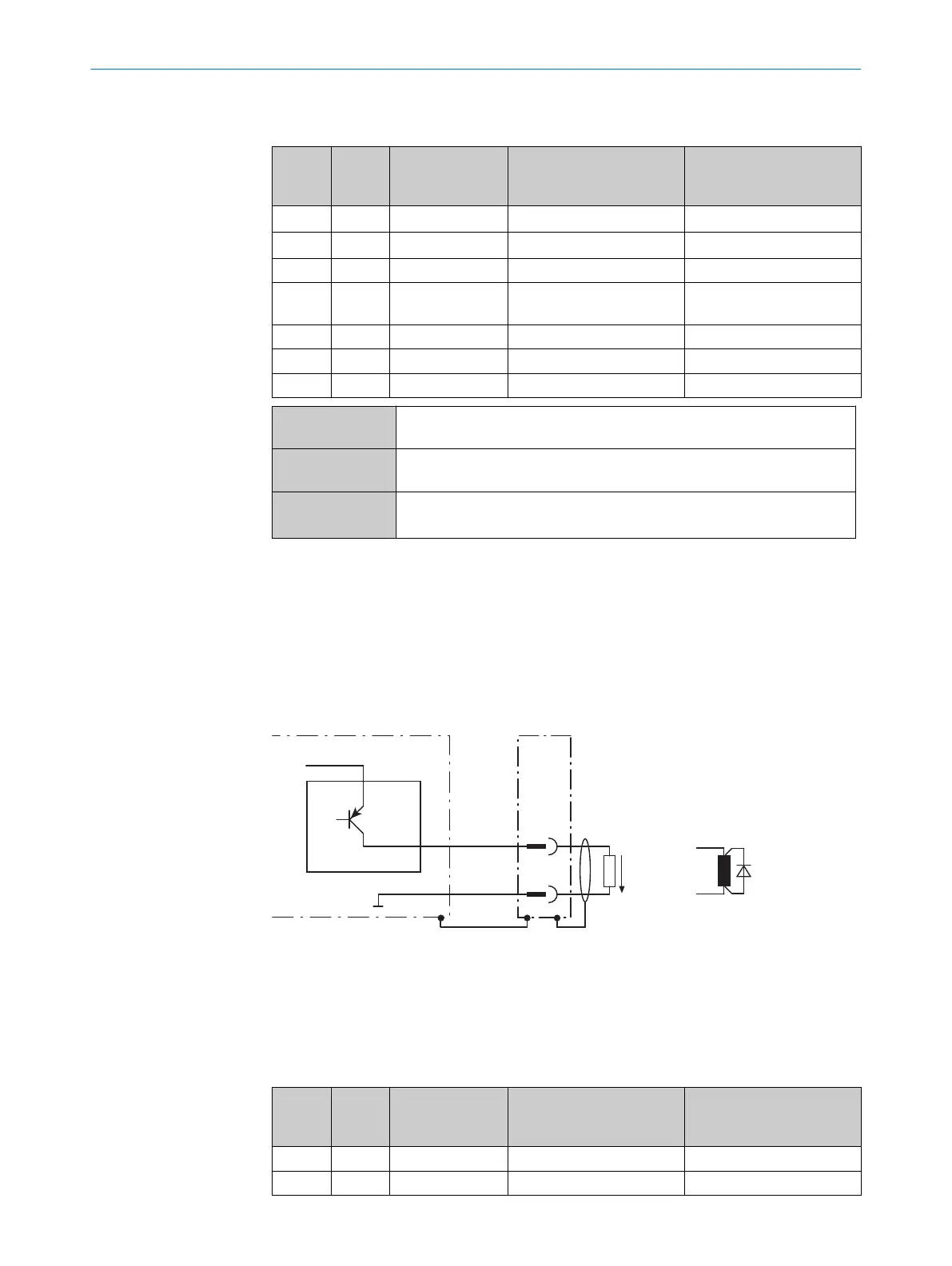
The structure and wiring principle of the digital outputs are shown below.
Device 1
OUT X 2
X
Y
GND
V
out
3
4
Figure 28: Wiring of digital output (PNP version)
1
Device
2
Signal OUT X
3
Output voltage V
out
4
If an inductive load is present: Provide an arc-suppression circuit at the digital switching
output. Attach a freewheeling diode directly to the load for this purpose.
Posi‐
tion
Signal TiM3xx-01xxxx
(cable with flying
leads): wire color
TiM3xx-10xxxx (15-pin D-
Sub-HD male connector):
PIN
TiM3xx-11xxxx,
TiM3xx-21xxxx (12-pin
M12 male connector): PIN
X1 OUT 1 Brown 12 5
X2 OUT 2 Orange 13 6
6 ELECTRICAL INSTALLATION
38
O P E R A T I N G I N S T R U C T I O N S | TiM3xx 8024851//2021-07-21 | SICK
Subject to change without notice