0
0
20
10
S
ar
S
ao
30
40
2020 1010 3030
1
3
2
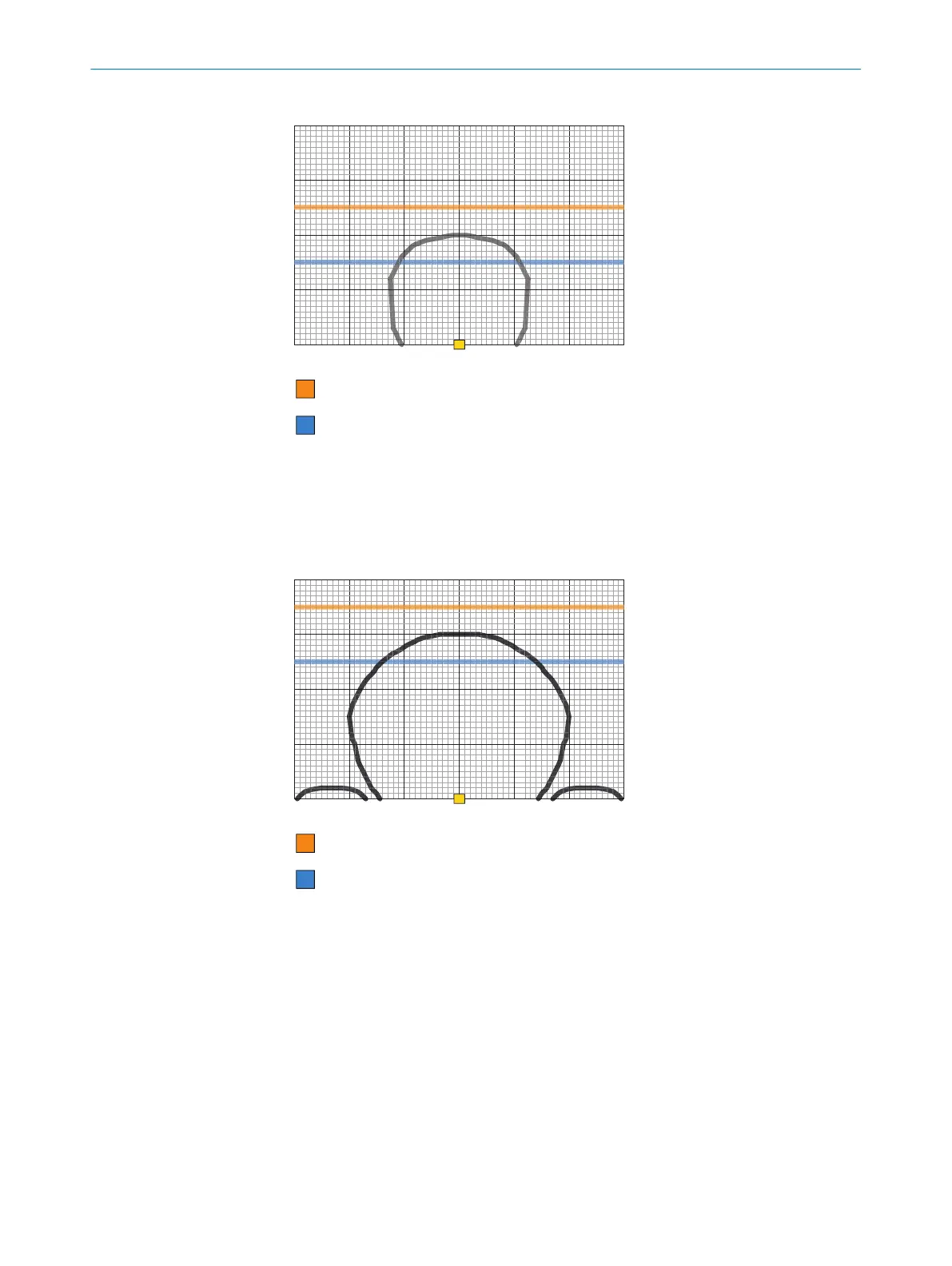
Figure 1: Response range with M18 actuator
1
Sensing range
2
Side deviation in mm
3
Distance to sensor surface in mm
0
3
2
0
20
10
S
ar
S
ao
30
40
2020 1010 3030
1
Figure 2: Response range with M30 actuator
1
Sensing range
2
Side deviation in mm
3
Distance to sensor surface
b
A minimum dis
tance of 3 mm (for M30 actuator) must be upheld when the actua‐
tor moves laterally to the sensor surface. This prevents early triggering due to the
side preparation areas.
b
If necessary, attach an additional protective stop for the moving part of the protec‐
tive device.
b
Observe the maximum tightening torque of 2.2 Nm for mounting the sensor and
actuator.
MOUNTING 4
8022968/15V1/2019-11-22 | SICK O P E R A T I N G I N S T R U C T I O N S | TR4 Direct Cylindrical
11
Subject to change without notice