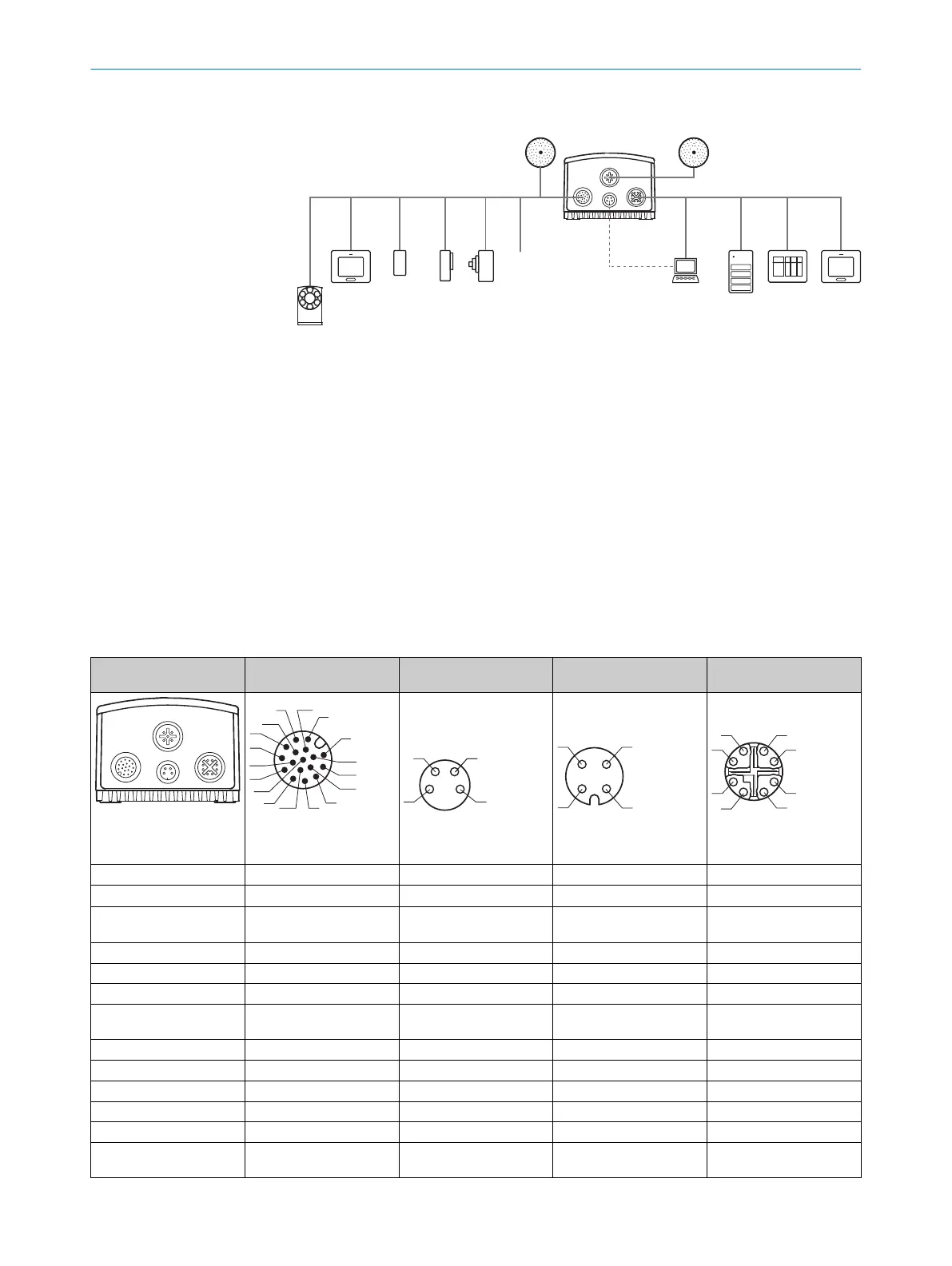
6.3.2 Example applications
Ethernet
USB
Lector
®
63x
Power I/O
External light
Ethernet
USB
External illumination ICL 1
V
S
External illumination
ICL, VLR, CCS 2
PC
FTP
SOPASSOPAS
Configuration 8
Image display 9
Diagnostics ß
HMI
PLC
PLC 5
Digital
switching
inputs 7
Digital
switching
outputs 6
serial 4
Ethernet
CSN (CAN sensor
network) 3
Figure 13: Facilities for connecting
1
External ICL illumination
2
External ICL, VRL, CCS illumination
3
CSN (CAN sensor network)
4
Serial
5
PLC (programmable logic controller)
6
Digital outputs, e.g. for signal lamps
7
Digital inputs e.g. for encoders, photoelectric sensors
8
Configuration
9
Image display
ß
Diagnostics
6.4 Pin assignments of electrical connections
Layout overview Power I/O
(Power/SerialData/CAN/I/O)
USB External illumination connec‐
tion
Ethernet
(Gigabit Ethernet)
Power I/O
External light
Ethernet
USB
3
1
7
2
6
5
4
8
13
14
17
15
9
10
12
16
11
Male connector, M12, 17-pin,
A-coded
Female connector, M8, 4-pin,
coded
Female connector, M12, 4-pin,
A-coded
Female connector, M12, 8-pin,
X-coded
PIN Signal Signal Signal Signal
1 GND DC +5 V V
S
1)
switchable output
2)
TRD0_P
2 V
S
1)
Data Trigger output for external illu‐
mination unit U
V
1)2)
TRD0_N
3 CAN L Data+ GND
2)
TRD1_P
4 CAN H GND ‒ TRD1_N
5 TD+ (RS-422), Host ‒ ‒ TRD3_P
6 TD- (RS-422), Host
TxD (RS-232), Host
‒ ‒ TRD3_N
7 TxD (RS-232), Aux ‒ ‒ TRD2_N
8 RxD (RS-232), Aux ‒ ‒ TRD2_P
9 SensGND ‒ ‒ ‒
10 Sensor 1, digital input ‒ ‒ ‒
11 RD+ (RS-422), Host ‒ ‒ ‒
12 RD- (RS-422), Host
RxD (RS-232), Host
‒ ‒ ‒
6 ELECTRICAL INSTALLATION
44
O P E R A T I N G I N S T R U C T I O N S | Lector63x Flex C-mount and S-mount 8018071/16XD/2020-05-06 | SICK
Subject to change without notice
 Loading...


