6.2.1 Data cables
NOTE
Layout of data cables
■
Use screened data cables with twisted-pair wires.
■
Implement the screening design correctly and completely.
■
To avoid interference, always use EMC-compliant cables and layouts. This applies,
for example, to cables for switched-mode power supplies, motors, clocked drives,
and contactors.
■
Do not lay cables over long distances in parallel with power supply cables and
motor cables in cable channels.
Serial data transmission (RS-232, RS422)
•
The possible length of cable between the device and host computer depends on
the following factors:
°
The physical version of the host interface selected
°
The data transmission rate set in the device
For further information, see "Wiring data interfaces", page 47.
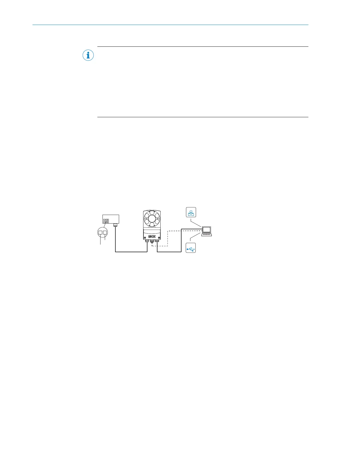
6.3 Connection diagrams
6.3.1 Connection principle
SOPASSOPAS
Configuration 3
Image display 4
Diagnostics 5
Power ...
Ethernet
USB 2
Cable 6 Cable 7
Connection
module 1
...
...
1
2
V
S
GND
USBUSB
EthernetEthernet
Lector
®
63x
Figure 12: Connection block diagram
1
Connection module CDB650-204 or CDM420-0006
2
Alternative USB, adapter cable (male connector, M8, 4-pin/male connector, USB, type A)
3
Configuration
4
Image display
5
Diagnostics
6
CDB650-204: Cable 1:1 (male connector, M12, 17-pin, A-coded/female connector, M12,
17-pin, A-coded)
CDM420-0006: Adapter cable (female connector, M12, 17-pin, A-coded/male connector,
D-Sub-HD, 15-pin)
7
Adapter cable (male connector, M12, 8-pin, X-coded/male connector, RJ45, 8-pin)
ELECTRICAL INSTALLATION 6
8018071/16XD/2020-05-06 | SICK O P E R A T I N G I N S T R U C T I O N S | Lector63x Flex C-mount and S-mount
43
Subject to change without notice
 Loading...


