Layout overview Power I/O
(Power/SerialData/CAN/I/O)
USB External illumination connec‐
tion
Ethernet
(Gigabit Ethernet)
13 Result 1, digital output ‒ ‒ ‒
14 Result 2, digital output ‒ ‒ ‒
15 Sensor 2, digital input ‒ ‒ ‒
16 Result 3, digital output ‒ ‒ ‒
17 Result 4, digital output ‒ ‒ ‒
1)
Supply voltage.
2)
Pin assignment for external ICL ring lighting.
Pin assignment for VLR illumination unit:
•
Pin 1: V
S
triggered
•
Pin 2: not assigned
•
Pin 3: GND
•
Pin 4: not assigned
The pins are assigned internally in the device by selecting the external ICL or VLR illumination using the SOPAS ET configuration software.
6.5 Connecting the device
6.5.1 Using the optional connection modules CDB and CDM
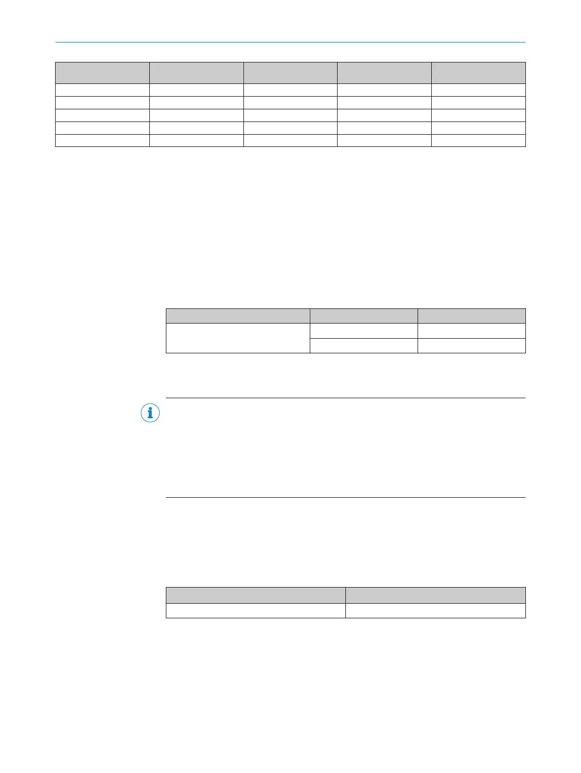
Table 9: Possible combinations of device and connection modules
Connection on the device Connection modules Connection cable
Male connector, M12, 17-pin, A-
coded
CDB650-204 Cable 1:1
1)
CDM420-0006
2)
Adapter cable
3)
1)
Connection cable 1:1 (female connector, M12, 17-pin, A-coded / male connector, M12, 17-pin, A-coded).
2)
CDM420-0007: for connecting 2 devices.
3)
Adapter cable (female connector, M12, 17-pin, A-coded / male connector, D-Sub-HD, 15-pin).
NOTE
Connection module
For detailed information about mounting and electrical installation, please refer to the
operating instructions for the connection module in question. These are available
online at.
•
www.sick.com/CDB
•
www.sick.com/CDM
6.5.2 Connecting the supply voltage
Voltage source in accordance with ES1 and PS2 (EN 62368-1) or SELV and LPS
(EN 60950-1).
The power source for the device must be able to provide the following power outputs:
Table 10: Required supply voltage V
S
Supply voltage V
S
Power source: required power output
1)
DC 12 V ... 24 V ± 20% Maximum 30 W
1)
For device with 4 loaded digital outputs (each 100 mA).
In the case of connection via the optional connection module CDB/CDM: additionally
required output power 0.5 W when using the optional parameter cloning module
CMC600 in the connection module.
ELECTRICAL INSTALLATION 6
8018071/16XD/2020-05-06 | SICK O P E R A T I N G I N S T R U C T I O N S | Lector63x Flex C-mount and S-mount
45
Subject to change without notice
 Loading...


