13 Annex
13.1 EU declaration of conformity / Certificates
The EU declaration of conformity and other certificates can be downloaded from the
Internet at:
•
www.sick.com/Lector63x
13.2 Dimensional drawings (electronic)
Current dimensional drawings in various electronic formats can be downloaded online:
•
www.sick.com/Lector63x
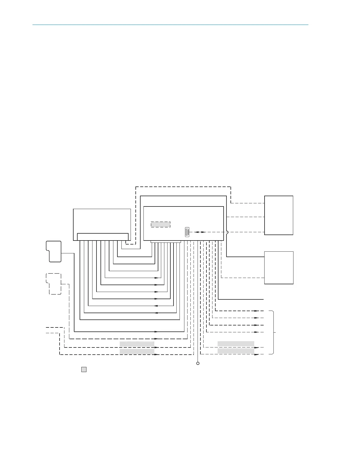
13.3 Connection diagrams of connection module CDB650-204
13.3.1 Connection of the device to CDB650-204
Device = Lector63x = V2D63xx-xxxxYx (Y = A, B or S)
„V
S
”
“Host 1”
“Aux 1”
“Result 2”
“Result 3”
“Result 4”
“Result 1”
“CAN”
“Sensor 2”
“Sensor 1”
“AUX”
CAN bus
“Result 1”
“Result 2”
PLC
“Result 3”
“Result 4”
“External output 2
CDB650-204
Connection module 6
“Host 1”
“Aux 1”
RS-232
HOST/PLC
Further data
processing 8
PC
Configuration
Diagnostics
Image display
Interfaces 3
Device 2
“Ethernet” (Host 2/Aux 2), Image transfer 5
“USB” (Aux 3) 4, Image transfer 5
RS-232/RS-422
Ethernet
USB
“Host 2”
Ethernet
“Aux 2”
“Aux 3”
“Sensor 2”
“Sensor 1”
“External input 2”
“External input 1”
CMC600
1
ã
â
V
S
ß
= á
“External output 1”
à 9
7
Figure 18: Connection of the device to peripherals via CDB650-204 (overview)
1
External trigger sensor, e.g. for read cycle generation
2
Device
3
Interfaces
4
USB interface only for temporary use (service)
5
Image transmission
13 ANNEX
72
O P E R A T I N G I N S T R U C T I O N S | Lector63x Flex C-mount and S-mount 8018071/16XD/2020-05-06 | SICK
Subject to change without notice
 Loading...


