Interpretation aid for the field of view diagrams
Using the diagrams, you can determine the following data for each device type:
•
The maximum working distance for a selected code resolution
•
The dimensions of the field of view that is available for this distance
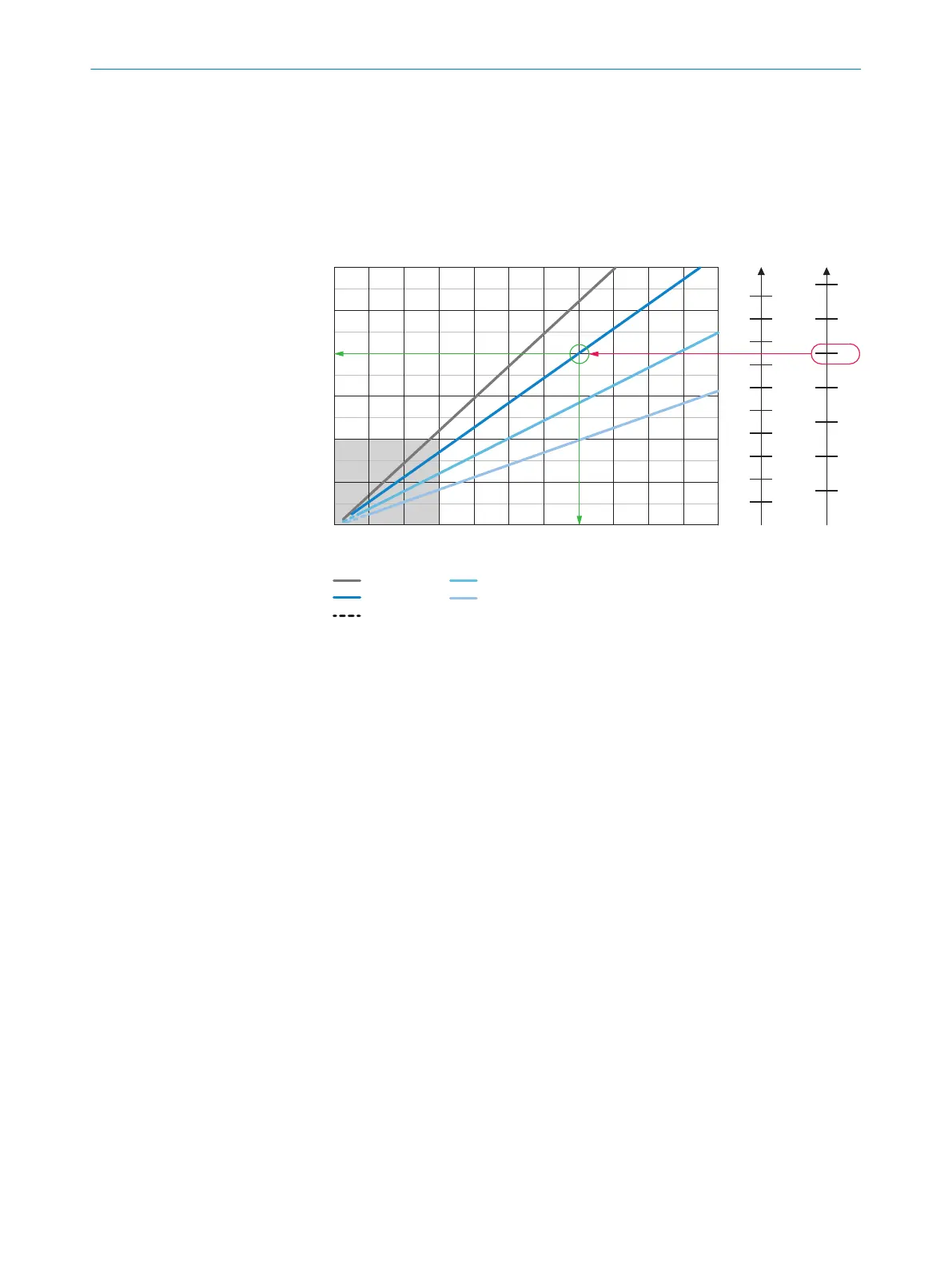
Example field of view diagram for Lector632 S-mount:
Min. resolution in mm 3
1D code 4 2D code 5
Field of view in mm² 1
0
0 200 400 600 800 1,000 1,200 1,400 1,600 1,800 2,000 2,200
400 x300
600 x450
800 x600
1,000 x750
1,200 x900
200 x150
0.1
0.3
0.5
0.7
0.9
0.2
0.4
0.6
0.8
1.0
1.2
1.4
a b
c
d
a: f = 9.6mm
b: f = 12.5mm
c: f = 17.5mm
d: f = 25.0mm
Optional spacer rings required à
7
8
9
Working distance/focus position in mm 6
ß
Complete area 2
1
Field of view in mm
2
2
Overall range
3
Minimum resolution in mm
4
1D code
5
2D code
6
Working distance/Focus position in mm
7
Selected code resolution
8
Focal length of lens, here example for f = 12.5 mm
9
Reading off: resultant maximum working distance
ß
Reading off: resultant field of view (mm x mm)
à
Optional spacer ring required
Given (in red):
•
Code resolution for 2D code 7: 1.0 mm
•
Focal length of lens 8: 12.5 mm
Read off (in green):
•
Maximum working distance 9: approx. 1,400 mm
•
Field of view ß: approx. 800 mm x approx. 600 mm
Both axes of the diagrams must be interpreted linearly.
5.6
Mounting the device
Aligning the device with viewing window to object
Remember to consider the shape and alignment of the field of view in front of the
device.
MOUNTING 5
8018071/16XD/2020-05-06 | SICK O P E R A T I N G I N S T R U C T I O N S | Lector63x Flex C-mount and S-mount
37
Subject to change without notice
 Loading...


