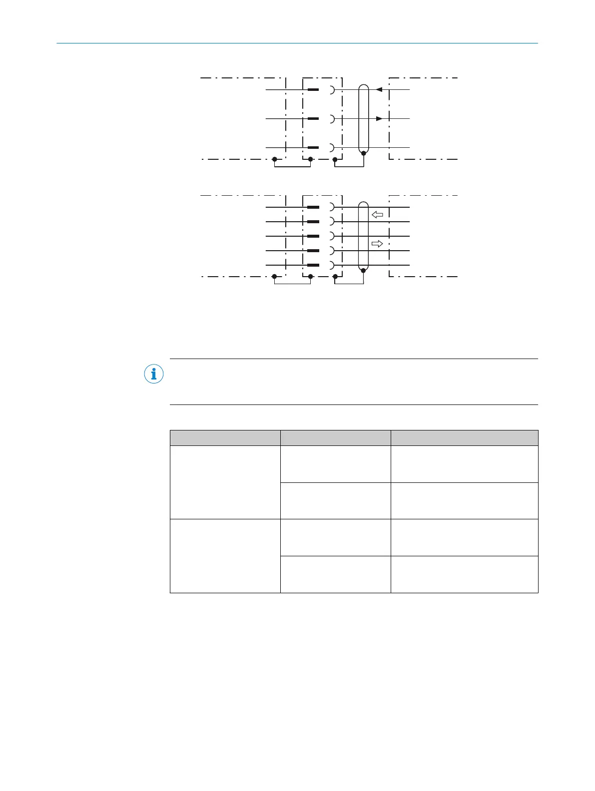
RS-232
!
"
§
Device 1 Host
TxD
RxD
GND
RxD
TxD
GND
RS-422
$
%
&
/
(
Device 1 Host
RD+
TD+
RD‒
TD‒
GND
TD+
RD+
TD‒
RD‒
GND
Figure 14: Wiring of the serial data interfaces RS-232 and RS-422
1
Device
!...§
Pin assignment: see RS-232 pin assignment for the respective device
$...(
Pin assignment: see RS-422 pin assignment for the respective device
NOTE
Activate the serial data interface type in the device using a configuration tool, e.g. the
SOPAS ET configuration software.
Wiring the data interfaces of the device via a connection module:
Connection module Data interface Reference
CDB650-204 RS-232 see "Wiring serial host interface
RS-232 of the device in
CDB650-204", page 75
RS-422 see "Wiring serial host interface
RS-422 of the device in
CDB650-204", page 76
CDM420-0006 RS-232 see "Connecting serial host interface
RS-232 of the device in
CDM420-0006", page 89
RS-422 see "Connecting serial host interface
RS-422 of the device in
CDM420-0006", page 89
Termination of the RS-422 data interface
Termination can be implemented in the connection module via switches.
Additional information on this can be found in the operating instructions for the relevant
connection module.
6 ELECTRICAL INSTALLATION
48
O P E R A T I N G I N S T R U C T I O N S | Lector63x Flex C-mount and S-mount 8018071/16XD/2020-05-06 | SICK
Subject to change without notice
 Loading...


