Counterclockwise rotation: Sensing range reduced
The sensing range can also be adjusted using just the potentiometer. We recommend
placing the object within the sensing range, e.g. see figure 7, page 35. Once the
sensing range has been adjusted, the object is removed from the path of the beam,
which causes the background to be suppressed. The digital output changes (table 4).
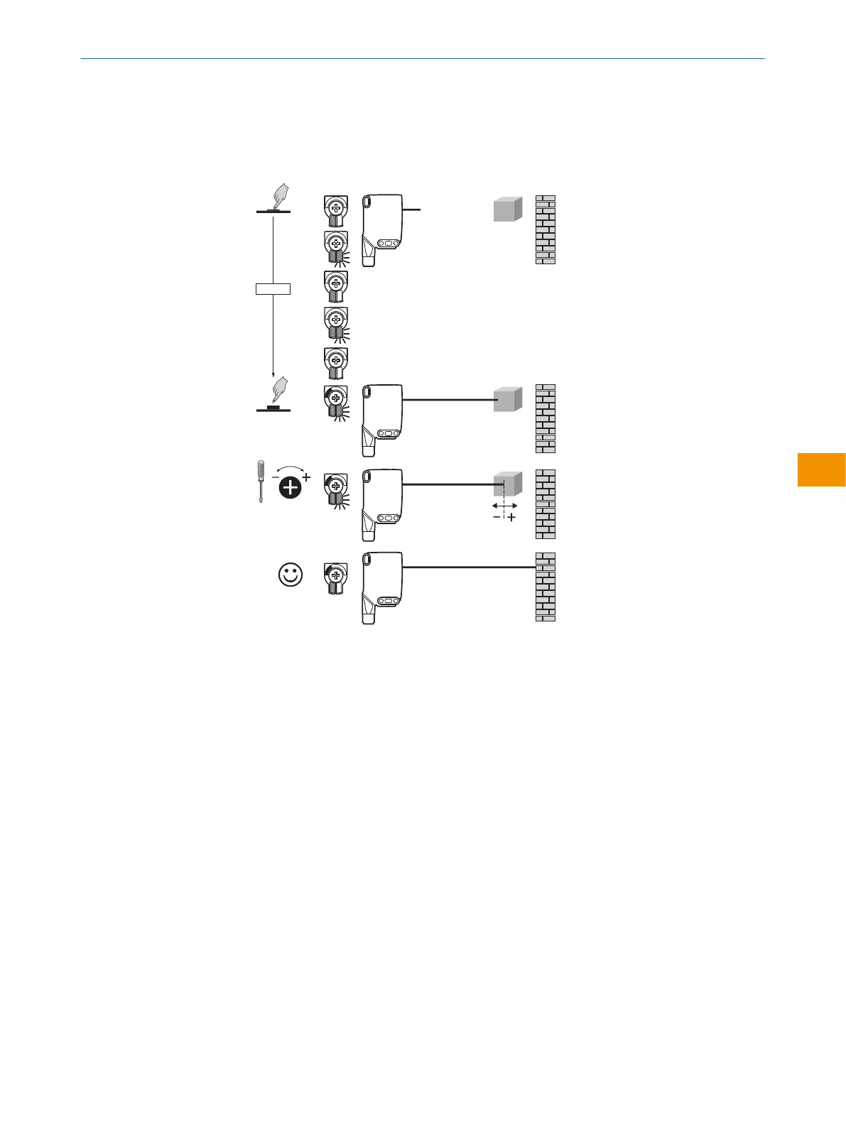
Figure 7: WTS26x-xxxxxx2xAxx, adjusting the sensing range with Teach-Turn adjustment
WTS26x-xxxxxx1xAxx with potentiometer:
The sensing range is adjusted with the potentiometer.
Clockwise rotation: Sensing range increased
Counterclockwise rotation: Sensing range reduced
We recommend placing the object within the sensing range, see figure 9for an exam‐
ple. Once the sensing range has been adjusted, the object is removed from the path of
the beam, which causes the background to be suppressed. The digital output changes
(table 4).
OPERATING INSTRUCTIONS
8020355.1GI9/2022-07-13 | SICK O P E R A T I N G I N S T R U C T I O N S | WTS26
35
Subject to change without notice
en