Technical data and characteristic curves
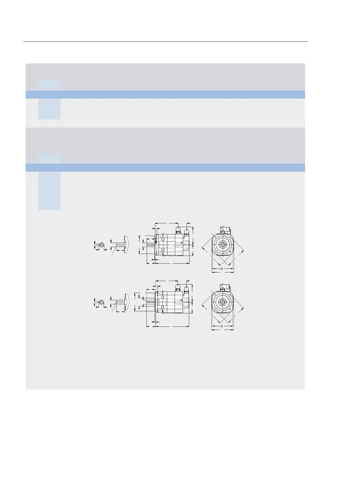
4.3 Dimension drawings
1FT7 Synchronous Motors
200 Configuration Manual, (PFT7S) 01/2009, 6SN1197-0AD13-0BP2
For motor Dimensions in mm (inches)
Power connector
Size 1
Shaft
height
Type DIN
IEC
a
1
P
b
1
N
c
1
LA
e
1
M
f
AB
f
1
T
f
3
–
g
2
–
h
–
o
1
–
s
2
S
1FT7 Compact, type of construction IM B5, water cooling, with connector, with/without brake
63 1FT7062
1FT7064
155
(6.10)
110
(4.33)
10
(0.39)
130
(5.12)
126
(4.96)
3.5
(0.14)
135
(5.31)
108
(4.25)
67
(2.64)
52
(2.05)
9
(0.35)
1FT7066
1FT7068
Flange 1
(1FT6-compatible)
Flange 0 DE shaft extension
without/with
brake
without/with
brake
Shaft
height
Type DIN
IEC
i
2
–
k
LB
o
–
b
2
–
i
2
–
f
2
–
k
LB
o
–
d
D
d
6
–
I
E
t
GA
u
F
63 1FT7062 50
(1.97)
208
(8.19)
141
(5.55)
51
(2.01)
56,5
(2.22)
6
(0.24)
202
(7.95)
135
(5.31)
24
(0.94)
M8 50
(1.97)
27
(1.06)
8
(0.31)
1FT7064 240
(9.45)
173
(6.81)
233
(9.17)
166
(6.54)
1FT7066 272
(10.71)
204
(8.03)
265
(10.43)
198
(7.80)
1FT7068 319
(12.56)
252
(9.92)
312
(12.28)
245
(9.65)
Flange 1
(1FT6-compatible)
1FT706
Flange 0
1FT706
e
1
f
a
1
Ø
d
Ø
b
1
1
1
oo
c
k
G_NC01_XX_00398
i
l
2
1
f
3
f
g
2
h
u
t
Ø
d
d
6
l
s
2
Shaft design
with fitted key
e
1
f
f
3
a
1
Ød
Øb
2
Øb
1
1
o
o
1
c
k
i
2
l
2
f
G_NC01_XX_00397
u
t
Ød
d
6
l
s
2
g
2
h

 Loading...


