Information on the application of motors
7.5 Mounting conditions
1FT7 Synchronous Motors
Configuration Manual, (PFT7S) 01/2009, 6SN1197-0AD13-0BP2
233
7.5 Mounting conditions
Some of the motor power loss is dissipated through the flange when the motor is connected
to the mounting flange.
Non-thermally insulated mounting
The following mounting conditions apply for the specified motor data:
Table 7- 3 Non-thermally insulated mounting conditions
Shaft height Steel plate, width x height x thickness [mm] Mounting surface[m
2
]
36 and 48 120 x 100 x 40 0,012
63 to 100 450 x 370 x 30 0,17
For larger mounting surfaces, the heat dissipation conditions improve.
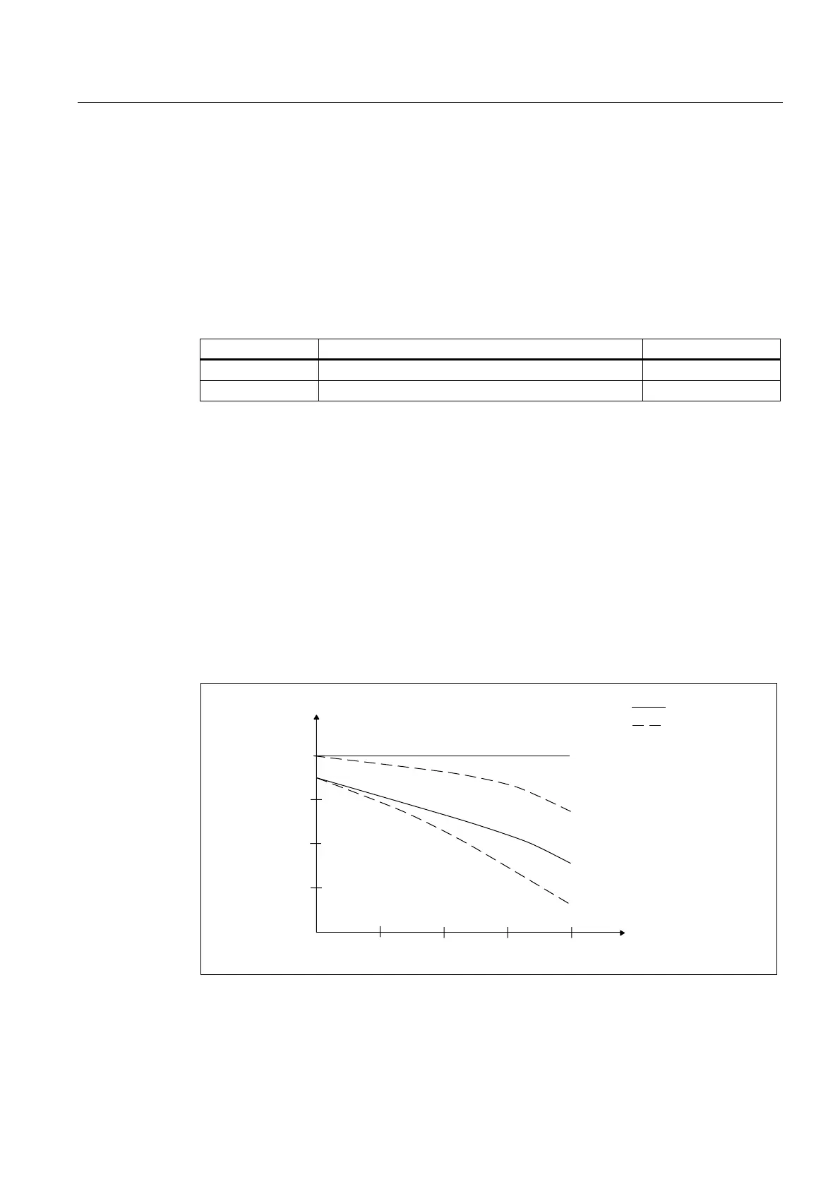
Thermally insulated mounting without additionally mounted components
For non-ventilated and force-ventilated motors, the static motor torque must be reduced by
between 5% and 15%. We recommend configuring the motor using the M
0 (60 K)
values. As
the speed increases, the reduction factor rises (see Fig. "Effect of the mounting conditions
on the S1 characteristic").
Thermally insulated mounting with additionally mounted components
● Holding brake (integrated in the motor). No additional torque reduction required
● Gearbox; the torque has to be reduced (see Fig. "Effect of the mounting conditions on the
S1 characteristics")
0
,QVXODWHG
6WUXFWXUH
ZLWKRXWJHDUER[
ZLWKJHDUER[
DSSUR[WR
1RQLQVXODWHG
6WUXFWXUH
Q1
Q
Figure 7-2 Effect of the mounting conditions on the S1 characteristic

 Loading...


