Motor components
5.3 Holding brake (option)
1FT7 Synchronous Motors
210 Configuration Manual, (PFT7S) 01/2009, 6SN1197-0AD13-0BP2
Table 5- 4 Example: Electronic components for the recommended circuit
Electr.
component
Examples
F 3RV10 circuit-breaker with current
paths connected in series (if
required with mounted auxiliary
contact 3RV1901 to provide a
feedback signal for the drive).
or Miniature circuit-breaker 5SX21 (if
required with mounted auxiliary contact
to provide a feedback signal for the
drive).
K1 Auxiliary contactor 3RH11 or Contactor 3RT10
R2 Varistor SIOVS14K30 (EPCOS)
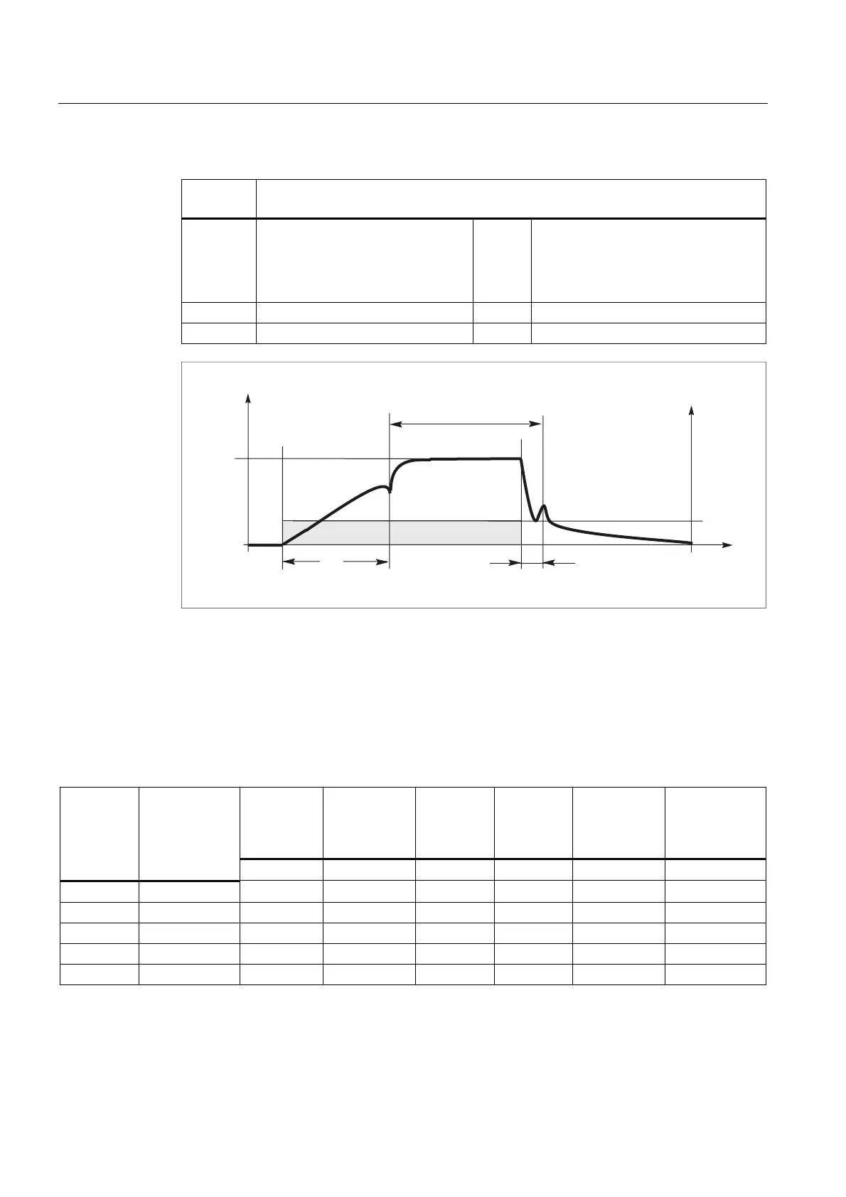
&XUUHQW,
W
,
9ROWDJH9
W
W
%UDNHRSHQHG
9
W RSHQLQJWLPH
W FORVLQJWLPH
PHDVXUHGDW9 9
F
F
Figure 5-3 Terminology (time) for holding operation
5.3.5 Technical data of the holding brake
Table 5- 5 Technical data of the holding brakes used for 1FT7 Compact motors
Holding
torque
M
4
at 120° C
Min. braking
torque
M
1
DC current
at 20 °C
Opening
time with
with varistor
Closing time
with varistor
Highest
switching
energy
Motor type Brake
designation
[Nm] [Nm] [A] [ms] [ms] [J]
1FT703 HT04P01 3 1,5 0,3 60 25 30
1FT704 HT07P01 8 5 0,6 90 30 270
1FT706 HT09P01 18 11 0,8 150 50 880
1FT708 HT11P01 48 25 1,0 220 65 1900
1FT710 HT14P01 85 35 1,6 250 70 5300

 Loading...


