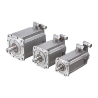
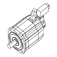
1FT7 Synchronous Motors
Configuration Manual, (PFT7S) 01/2009, 6SN1197-0AD13-0BP2
241
Appendix
A
A.1 Description of terms
Braking resistance R
opt
R
opt
corresponds to the optimum resistance value per phase that is switched in series
external to the motor winding for the armature short-circuit braking function.
Braking torque M
br eff
M
br eff
corresponds to the average braking torque for armature short-circuit braking that is
achieved through the upstream braking resistor R
opt
.
Cyclic inductance L
D
The cyclic inductance is the sum of the air gap inductance and leakage inductance relative to
the single-strand equivalent circuit diagram. It consists of the self-inductance of a phase and
the coupled inductance to other phases.
DE
Drive end = Drive end of the motor
Electrical time constant T
el
Quotient obtained from the rotating field inductance and winding resistance. T
el
= L
D
/R
ph
Maximum converter current I
max conv
RMS converter output current (per phase) that can be supplied temporarily by the
recommended motor module
Max. current I
max, RMS
This current limit is only determined by the magnetic circuit. Even if this is briefly exceeded, it
can result in an irreversible de-magnetization of the magnetic material. Specification of the
RMS value of a sinusoidal current.
Moment of inertia J
mot
Moment of inertia of rotating motor parts.

 Loading...


