Configuration
2.4 Procedure when engineering
1FT7 Synchronous Motors
50 Configuration Manual, (PFT7S) 01/2009, 6SN1197-0AD13-0BP2
J
M
Motor moment of inertia
J
G
Gearbox moment of inertia
J
load
Load moment of inertia
n
Load
Load speed
i Gear ratio
η
G
Gearbox efficiency
M
load
Load torque
M
R
Frictional torque
T Cycle time, clock cycle time
A; E Initial value, final value in time slice Δ
t
i
t
e
ON period
∆t
i
Time interval
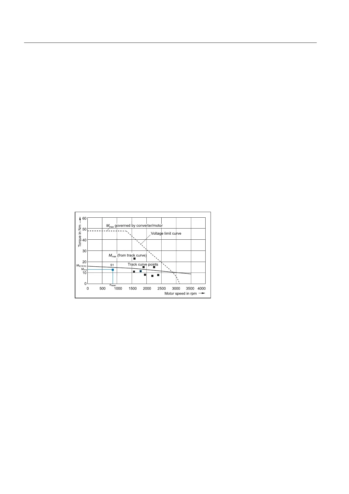
The RMS torque M
rms
must lie below the S1 curve.
The maximum torque M
max
is produced during the acceleration operation. M
max
must lie
below the voltage limiting characteristic curve. In summary, the motor is selected as follows:
Figure 2-7 Selecting motors depending on the load duty cycle (example)
Specification of the motor
Through variation, it is now possible to identify a motor which meets the requirements of the
application (duty cycle).
In a second step, a check is made as to whether the thermal limits are maintained. To do
this, the motor current at the base load must be calculated. The calculation depends on the
type of motor used (synchronous motor, induction motor) and the particular application (duty
cycle). When configuring according to duty cycle with constant ON period with overload, the
overload current must be calculated relative to the required overload torque.
Finally, the other motor features must be defined by configuring the motor options.

 Loading...


