Mechanical properties of the motors
3.2 Liquid cooling
1FT7 Synchronous Motors
56 Configuration Manual, (PFT7S) 01/2009, 6SN1197-0AD13-0BP2
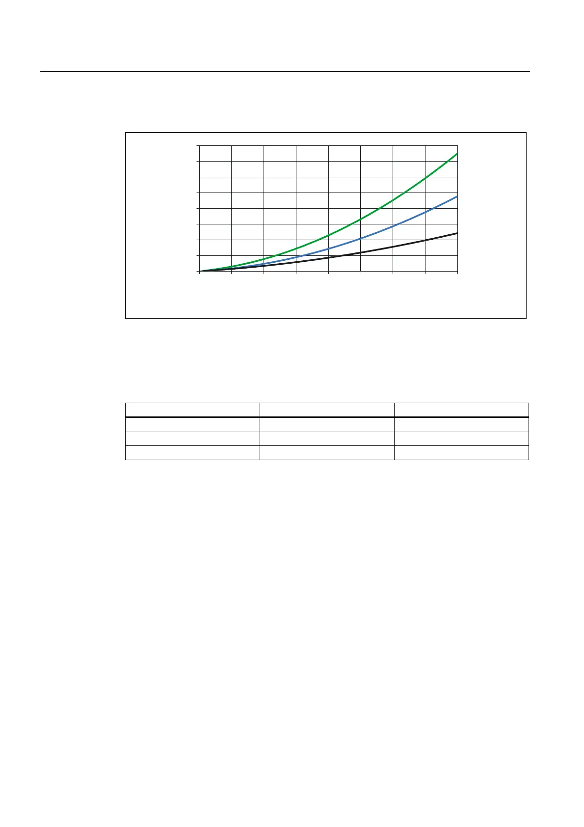
Pressure loss in the motor
)7[
)7[
)7[
'XUFKIOXVVPHQJH>OPLQ@
)ORZUDWH>OPLQ@
'UXFNDEIDOO>03D@
'HFUHDVHLQSUHVVXUH>DWP@
Figure 3-2 Pressure loss 1FT7
The nominal coolant flows specified in the following table must be maintained in order to
ensure sufficient cooling.
Table 3- 4 Pressure loss at the nominal coolant flow
Shaft height Flow rate Pressure loss
1FT706x 3 l/min 0.03 MPa
1FT708x 4 l/min 0.03 MPa
1FT710x 5 l/min 0.025 MPa
Pressure balancing
If various components are connected in the cooling circuit, pressure balancing may be
necessary. Reactor elements must be fitted at the coolant outlet for the motor or the relevant
components.
Avoiding cavitation
During uninterrupted duty, the pressure drop by an inverter or motor must not exceed
0.2 MPa. Otherwise the high volumetric flow will lead to cavitation or abrasion damage.
Connecting motors in series
For the following reasons, connecting motors in series is only recommended under certain
conditions:
● The necessary volumetric flows of the motors must be within a similar order of magnitude
(< factor 2)
● The temperature rise in the coolant can lead to derating in the second or third motor if the
maximum coolant intake temperature is exceeded.

 Loading...


