Technical data and characteristic curves
4.1 Operating range and characteristics
1FT7 Synchronous Motors
74 Configuration Manual, (PFT7S) 01/2009, 6SN1197-0AD13-0BP2
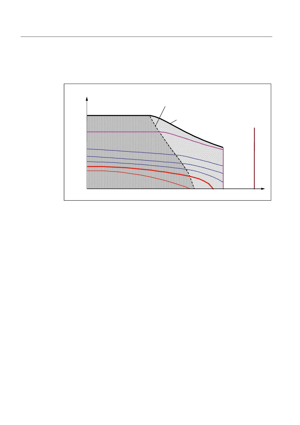
Torque limit when operating on a SINAMICS S120 drive system without field weakening
It is possible to deactivate the field weakening function with the SINAMICS S120 drive
system. This reduces the available operating range.
0RWRUVSHHG>USP@
ZLWKRXWILHOG
ZHDNHQLQJ
)LHOGZHDNHQLQJUDQJH
9ROWDJHOLPLWLQJFKDUDFWHUL
VWLFZLWKILHOGZHDNHQLQJ
9ROWDJHOLPLWLQJFKDUDFWHULVWLFZLWKRXW
ILHOGZHDNHQLQJ
0>1P@
6.
6.
6
6
6
0
PD[
0
PD[
LQY
Q
PD[LQY
Q
PD[PHFK
Figure 4-2 The shape of the voltage limiting characteristic curve is determined by the winding
version (armature circuit) and the magnitude of the converter output voltage.
The voltage induced in the motor winding increases as the speed increases. The difference
between the DC link voltage of the converter and the induced motor voltage can be used to
apply the current.
This limits the applicable current level. This causes the torque to drop off quickly at high
speeds. All operating points that can be achieved with the motor lie to the left of the voltage
limiting characteristic curve shown as a dashed line.
The characteristic curve is plotted for each winding version in a separate data sheet. The
torque-speed diagrams for different inverter output voltages are then assigned to each data
sheet:
Diagram [a] 380 V
Diagram [b] 425 V
Diagram [c] 460 V
For different converter output voltages the voltage limiting characteristic curve must be
shifted (offset) accordingly. See "Offset of the voltage limit characteristic" For 1FT7
Compact, the voltage limiting characteristic is calculated for a motor at operating
temperature.

 Loading...


