Transport, assembly, and connection
3.3 Electrical connection
A5E00215731A AD
30 Siemens AG Operating Instructions 2.02 1PL618
1P
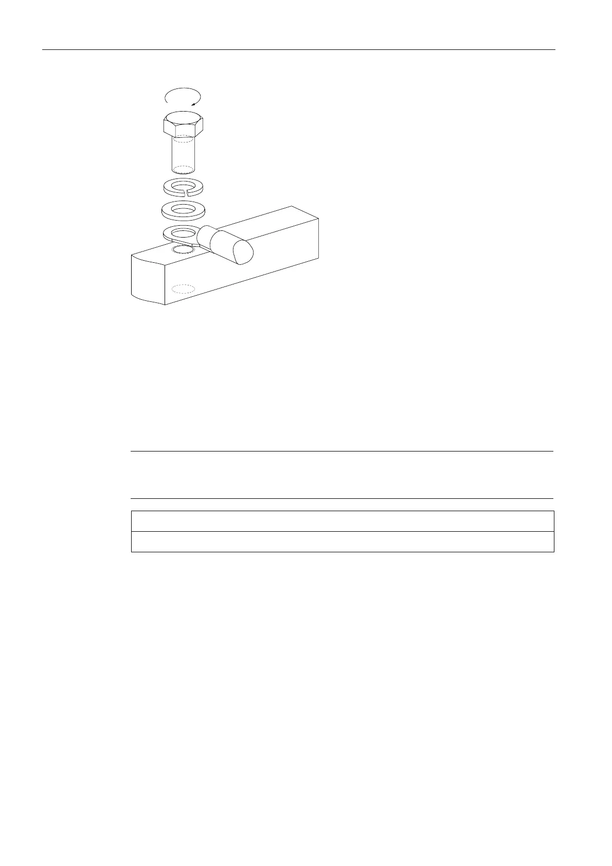
Figure 3-3 Tightening torques for contact nuts and mounting bolts
① contact nut
② mounting bolt
Principles of fitting and laying cables
Lead in permanently laid entries using EMC cable glands. Screw the cable glands into the
threaded holes in the entry plate, which can be unscrewed.
Arrange the exposed connecting cables in the terminal box such that the PE conductor has
excess length and the insulation of the cable strands cannot be damaged.
Note
We recommend you use shielded cables whose shields are conductively connected to a
large area of the metal terminal box of the motor (with an EMC cable gland made of metal).
NOTICE
Unused threads must be sealed with a metallic screw plug.
Internal equipotential bonding
The equipotential bonding between the ground terminal in the terminal box housing and the
motor frame is established via the terminal box mounting bolts. The contact points
underneath the bolt heads are bare metal and are protected against corrosion.
The standard terminal box cover mounting screws are adequate as potential bonding
between the terminal box cover and terminal box itself.
Final checks
Before closing the terminal box, please check that:
 Loading...