Home
Siemens
Controller
6ES7 305-1BA80-0AA0
Siemens 6ES7 305-1BA80-0AA0 Product Information
4
of 1
of 1 rating
208 pages
Give review
Manual
Specs
To Next Page
To Next Page
To Previous Page
To Previous Page
Loading...
Commissioning
3.7 Diagnosing the techn
ology configurat
ion
Connection of the SINAMICS S120 to the Technology CPU
90
Product Information, 09/2011, A5E00480378-04
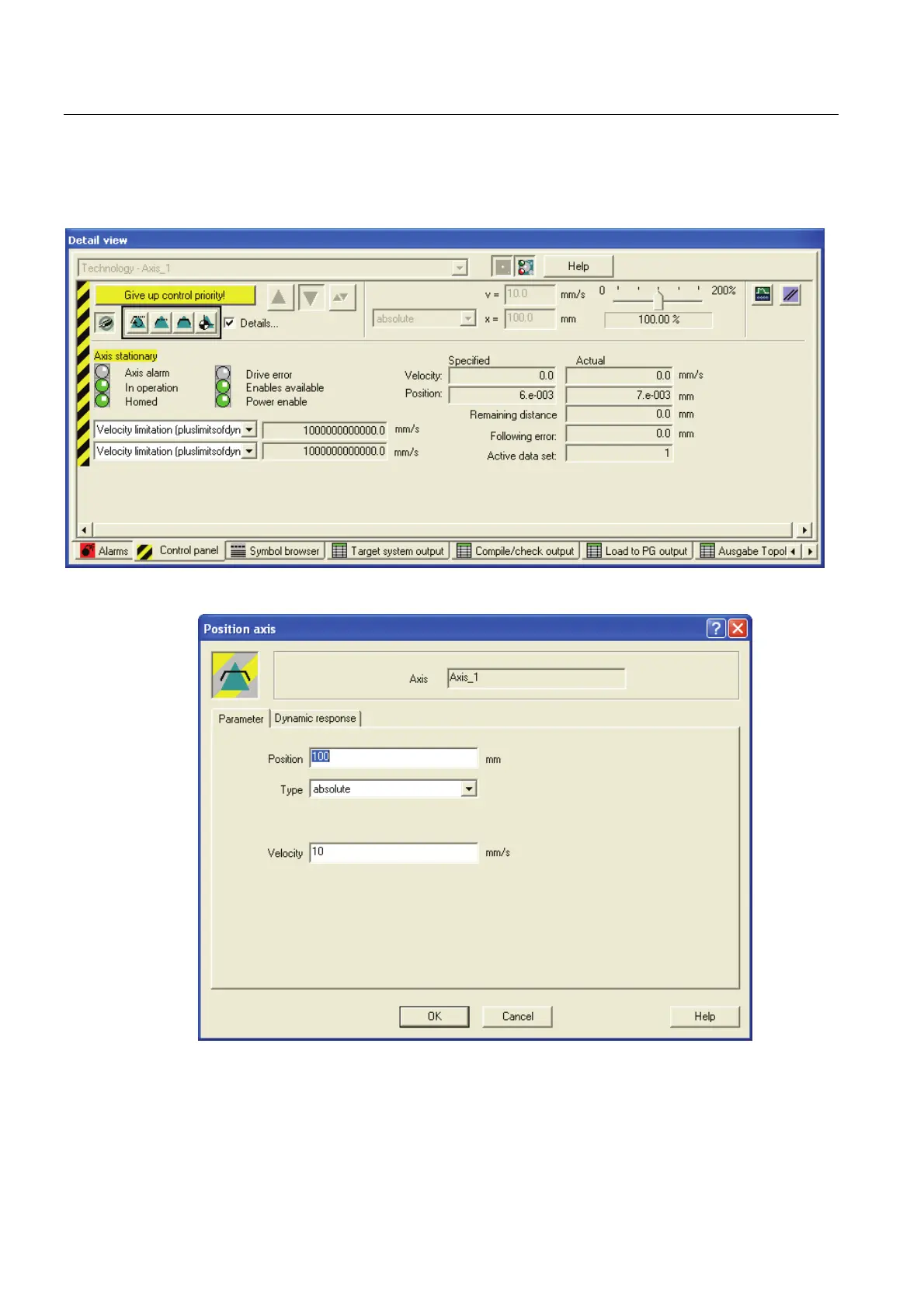
Depending on the selected operating mode of the axis, various p
arameters for the axi
s
motion can be specified in an additio
nal input window.
Example: Positioning axis
89
91
Table of Contents
Default Chapter
3
Table of Contents
3
1 Definitions and Warnings
7
2 SINAMICS S120 Automation Components
9
System Overview
9
Control Unit
9
Line Modules
10
Motor Modules
10
Expansion and System Components
11
Determining the Firmware Version Number
11
SINAMICS Support Packages
13
3 Commissioning
15
Commissioning Procedure
15
Connecting Hardware Components
15
PROFIBUS Interconnection
15
Interconnection of the DRIVE-Cliq Components
17
Additional Hardware Wiring for Smart Line Modules Without DRIVE-Cliq
21
Special Features of the SINAMICS S120 Training Case
22
Preparing the Connection to the SINAMICS
23
Overview
23
Creating a STEP 7 Project
23
Configuring in HW Config
24
Activating Routing in Netpro
30
Configuring the Drive Components
35
Overview
35
Automatic Configuring
35
Manual Configuring
39
Alignment of the Profidrive Message Frames
69
Loading the Configuration into the Drive Components
70
Optimizing the Speed Controller in the Drive
71
Diagnosing the SINAMICS Configuration
75
Checking the DRIVE-Cliq Wiring Online
75
Drive Test Using the SINAMICS Control Panel
76
Creating Technology Objects
78
Creating and Configuring Axes
78
Technology Objects Management (TOM)
85
Diagnosing the Technology Configuration
87
Overview
87
Preparations
87
Axis Test Using the Technology Axis Control Panel
89
Creating the User Program
91
Using Technology Functions
91
Special Considerations for the Use of an Active Line Module
91
4 Basic Functions
93
Encoder Settings
93
Encoder Configuration (Overview)
93
Characteristic Values for Encoders
93
Structure of the Encoder Actual Values
95
Encoder Types
99
Encoder Mode
100
Setting Encoder Parameters in the Technology
100
Display of the Encoder Parameters in S7T Config
102
Homing
104
Homing Possibilities
104
Example: Active Homing with Homing Output Cam and Encoder Zero Mark
105
Example: Active Homing Using Only an External Zero Mark
109
Example for Active Homing with One of the External Zero Marks Mirrored on the T-CPU
114
Example: Active Homing Using Only an Encoder Zero Mark
117
Absolute Encoder Adjustment with the Control Panel
120
Triggering of the Integrated Outputs of the CU 320 Control Unit
122
5 Expert Functions
127
Profidrive Message Frame
127
Message Frame Types
127
Example: Telegram 105
129
Extending a Profidrive Message Frame
130
Address Areas
130
Extending a Message Frame by Creating Additional Components
131
Extending the Profidrive Message Frame in S7T Config
138
Extending an Existing PROFIBUS Message Frame for the Drive
139
Disabling the PROFIBUS Sign-Of-Life Monitoring
145
Activating a Second Encoder
146
Using a Second Encoder
146
Connecting a Second Encoder in SINAMICS
148
Reading the Drive Parameters
150
Example: Reading Several Parameters Using "Mc_Readdriveparameter
150
Measuring Function
152
Use Cases
152
Measuring Using the Integrated Inputs on the CU320
156
Fetching the Measuring Inputs Using the TM17 Terminal Module
159
Triggering an Output Cam Using the TM17 Terminal Module
165
Triggering of a Brake
174
Vertical Axis Application Case
174
Activating Braking Sequential Control in SINAMICS
174
Activating Braking Sequential Control in the Axis
176
6 Safety Integrated Functions in SINAMICS Drive Systems
183
Safety Integrated Functions - Overview
183
Safety Integrated Functions in SINAMICS S120 Drive Systems
184
Support of SINAMICS Safety Integrated Functions by the T(F)-CPU
186
Support of the SINAMICS Safety Integrated Functions - Overview
186
Activating the Support of SINAMICS Safety Integrated Functions
187
Message Frame Structure
188
Extension of Actual Value Message Frame in S7T Config
190
Configuration Data of the Axis Technology Object
194
Safety Status Displays and Error Messages
195
Behavior and Reactions in the User Program
198
Safety Integrated Functions Without Configured Support of the Extended Functions
202
Control Via Profisafe
203
Other manuals for Siemens 6ES7 305-1BA80-0AA0
Manual
594 pages
Reference Manual
574 pages
Hardware And Installation Manual
242 pages
Technical Data
244 pages
Technical Data Manual
252 pages
Quick Start
82 pages
Operating Instructions
5 pages
Function Manual
332 pages
Equipment Manual
79 pages
Installation And Hardware Manual
20 pages
Getting Started
100 pages
4
Based on 1 rating
Ask a question
Give review
Questions and Answers:
Need help?
Do you have a question about the Siemens 6ES7 305-1BA80-0AA0 and is the answer not in the manual?
Ask a question
Siemens 6ES7 305-1BA80-0AA0 Specifications
General
Brand
Siemens
Model
6ES7 305-1BA80-0AA0
Category
Controller
Language
English
Related product manuals
Siemens 6ES7 331-7SF00-0AB0
112 pages
Siemens 6ED1 052-1HB00-0BA2
236 pages
Siemens 6ED1 052-2MD00-0BA2
236 pages
Siemens 6ED1 052-1MD00-0BA2
236 pages
Siemens 6ED1 052-1CC00-0BA2
236 pages
Siemens 6ED1 053-1FB00-0BA2
236 pages
Siemens 6ED1 053-1FH00-0BA2
236 pages
Siemens 6MD86
1256 pages
Siemens RWF55.6
93 pages
Siemens LFL1.635
25 pages
Siemens QAA78.610
221 pages
Siemens SIMODRIVE 611 universal
930 pages
 Loading...


