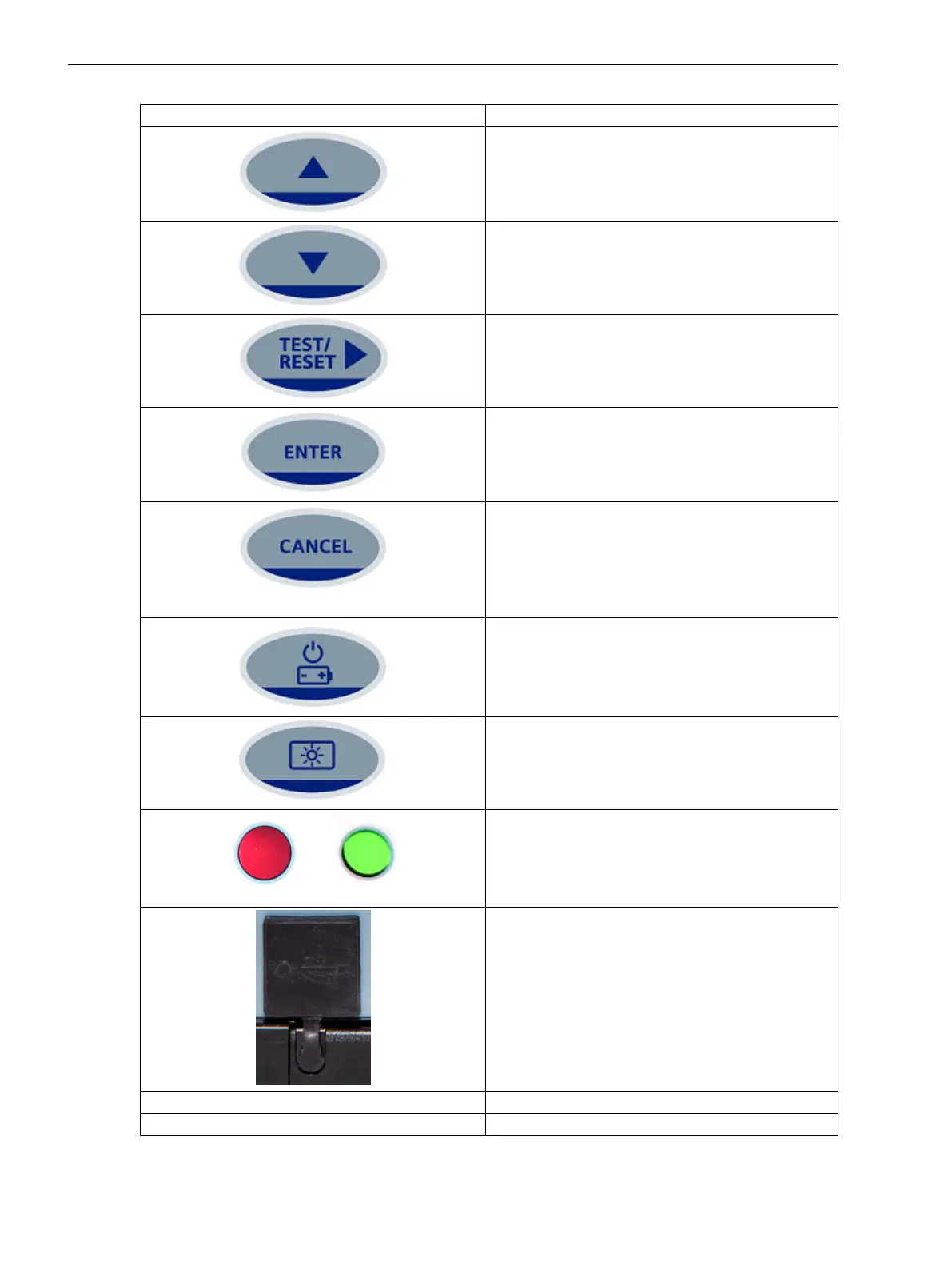
Operator Element/Display Element Function
Navigate the menu structure or to increase the param-
eter value in the edit mode.
Navigate the menu structure or to decrease the
parameter value in the edit mode.
To reset the fault indication on the fascia. Also used
for selecting the menu or selecting parameter values
in the edit mode. You can acknowledge the LEDs,
binary output, and trip flag indication.
Used for selecting the parameter or confirming the
values. The ENTER push-button is used to initiate and
accept the setting changes. Press ENTER to edit the
parameter setting. The setting value flashes and can
be changed by using the ▲ or ▼ keys.
Used to return the relay display to its initial status or
one level up in the menu structure. Press CANCEL to
return to the previous menu or to cancel the value.
This push-button is used to reject any alterations to a
setting while in the edit mode. Press the CANCEL key
repeatedly to return to the Relay Identifier screen.
Used to power on and power off the relay with battery
power when the auxiliary power, CT power, and USB
power are not available.
Used to turn on and turn off the backlight.
Local Flag
The status of the flag is GREEN in normal condition
and turns RED during the trip condition.
USB port
1 USB port with a silicon rubber cover.
The USB port connection can be used for updating
settings via Reydisp Evolution and uploading firm-
ware.
LED 2 TRIP (Red LED) The trip indication for the phase/earth faults
LED 3 PICKUP (Amber LED) The pickup indication for the phase/earth faults
Using the Relay Fascia
4.4 Overview of Operator Elements and Display Elements
50 Reyrolle, Operating, Manual
C53000-B7040-C101-1, Edition 08.2020
 Loading...