Technical Description, Installation Instructions, Operation
17
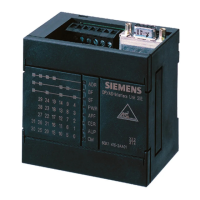
DP/AS-Interface Link 20E
Release 11/2002
C79000-G8976-C138–04
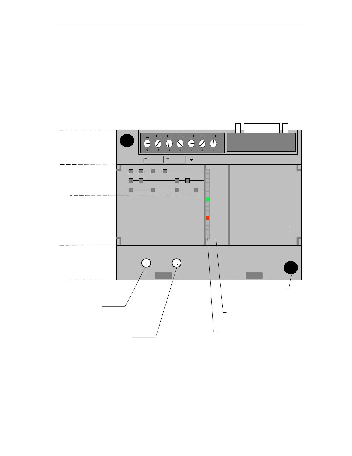
1.5 Front Panel – Access to all Functions
Connection, Display and Control Elements
On the front panel, you have access to all the connection, display and control
elements of the DP/AS-i Link 20E module.
In operation, the connection and control elements are protected by a front cover.
PWR
APF
CER
AUP
CM
DP/AS-Interface Link 20E
6GK1 415-2AA01
1
2
3
4
5
6
7
8
0
9
10
11
12
13
14
15
16
17
18
19
20
21
22
23
24
25
26
27
28
29
30
31
X 2
3 4
DISPLAY
*
)
*
)
SET
1 PROFIBUS DP
BF
SF
ADR
Connection Elements
(front cover open)
Control Elements
(front cover open)
Group Display
– 3 LEDs
Slave Display
– 5 LEDs
SET Button
– For AS-i configuration
– For setting the
PROFIBUS address
DISPLAY Button
– Changes over the display
Labeling Field
status display
LED Row
with 8 two-color LEDs
(red/green or yellow/green) for
– status display
or
– group/slave display
Display elements
Mounting hole
for
wall installation
Figure 1-2 Front Panel
Connections, Operator Controls and Interpreting the Displays
For more detailed information, refer to the following sections.