Technical Description, Installation Instructions, Operation
18
DP/AS-Interface Link 20E
Release 11/2002
C79000-G8976-C138–04
1.6 Connection Elements
Connections
The DP/AS-i Link 20E module has the following connections:
S Two connections to the AS-i cable (bridged internally)
S One connection for functional earth
S One connection to PROFIBUS (9-pin sub D female connector)
The connectors are located below the upper cover of the front panel of the
DP/AS-i Link 20E module.
Connections to the AS-i cable
The DP/AS-i Link 20E module has two connections for AS-i cables that are
jumpered internally in the DP/AS-i Link 20E module.
This allows the DP/AS-i Link 20E module to be looped into the AS-i cable.
!
Caution
The permitted current loading of the AS-i connection contacts is 3 A. If this
value is exceeded on the AS-i cable, the DP/AS-i Link 20E module must not
be looped into the AS-i cable but must be connected with a tap line (only
one pair of connectors of the DP/AS-i Link 20E module is used).
The DP/AS-i Link 20E module is supplied with power entirely from the
AS-Interface.
The current consumption from the AS-Interface is 200 mA.
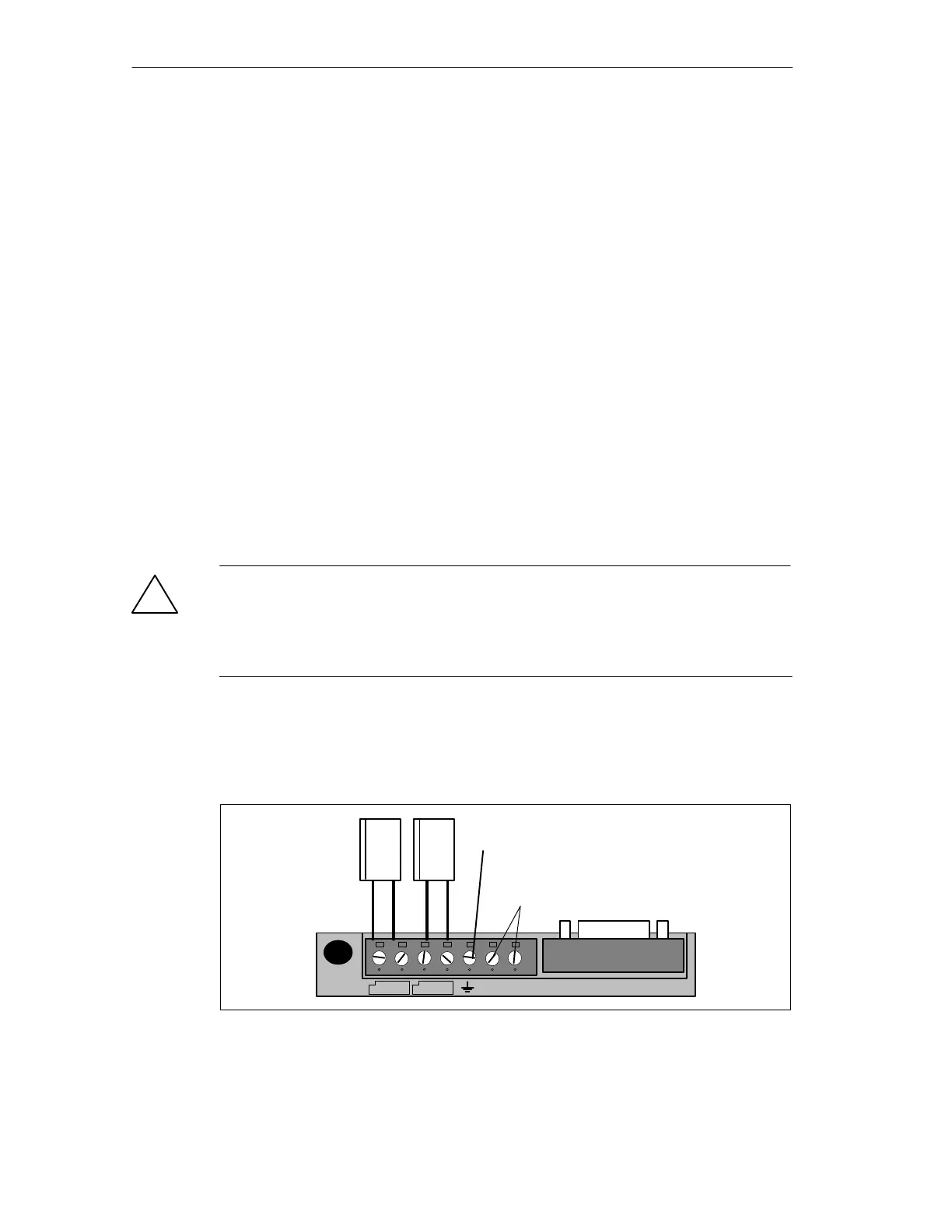
–
+
–
+
1 PROFIBUS DP
AS-i cables
Connections
not used
Functional ground
Figure 1-3 Connection of the AS-i Cable