Technical Description, Installation Instructions, Operation
20
DP/AS-Interface Link 20E
Release 11/2002
C79000-G8976-C138–04
1.7 Display and Control Elements
Meaning of the ADR, BF and SF LEDs
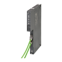
The front panel of the DP/AS-i Link 20E module has a row with 8 LEDs (see Figure
1-2). All the LEDs are 2-color (red/green or yellow/green). The upper three LEDs
(ADR, BF and SF) make up the group display. They indicate the display status.
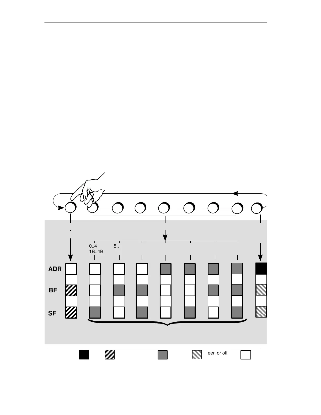
Changing the Display Status – DISPLAY Button
The following figure shows the possible display statuses of the group display.
You can change between the status display, slave display and PROFIBUS display
with the DISPLAY button. Each time you press the button, you change to the next
display status finally returning to the initial status.
ADR
BF
SF
0..4
1B..4B
5..9
5B..9B
10..14
10B..14B
20..24
20B..24B
25..29
25B..29B
30..31
30B..31B
15..19
15B..19B
PROFIBUS
address
display
red red or off green green or off off
Change to next display status
with the DISPLAY button
Status display
(initial status)
Display of the AS-i slaves
Key:
Static display: AS-i standard slaves and A slaves
Flashing display: B slaves