Technical Description, Installation Instructions, Operation
22
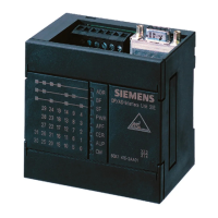
DP/AS-Interface Link 20E
Release 11/2002
C79000-G8976-C138–04
Table 1-2 , (continued)
LED (color) MeaningStatus
CER (yellow) Configuration
Error
This LED indicates whether the slave configuration detected on the
AS-i cable matches the expected configuration on the
DP/AS-i Link 20E module. If they do not match, the “CER” LED is lit.
The “CER” LED is lit in the following situations:
S When a configured AS-i slave does not exist on the AS-i cable (for
example failure of the slave).
S When an AS-i slave exists on the AS-i cable but it was not
previously configured.
S When an attached AS-i slave has different configuration data (I/O
configuration, ID code) from the slave configured on the
DP/AS-i Link 20E.
S When the DP/AS-i Link 20E module is in the offline mode.
AUP (green) Autoprog
available
In the protected mode of the DP/AS-i Link 20E module, the LED
indicates that automatic address programming of an AS-i slave is
possible. The automatic address programming makes it much easier
to exchange a defective AS-i slave on the AS-i cable (for more
detailed information refer to Chapter 5.1).
CM (yellow) Configuration
Mode
This LED displays the mode of the DP/AS-i Link 20E module.
S LED lit: configuration mode
S LED unlit: protected mode
The configuration mode is only required for installing and starting up
the DP/AS-i Link 20E module. In the configuration mode, the
DP/AS-i Link 20E module activates all connected AS-i slaves and
exchanges data with them. For more information about the
configuration mode, refer to Section 1.8.