Technical Description, Installation Instructions, Operation
26
DP/AS-Interface Link 20E
Release 11/2002
C79000-G8976-C138–04
6. When all the bits have been entered, the display of the set address bits
alternates quickly red/green or yellow/green. If you press the SET button again,
the set PROFIBUS address is adopted by the DP/AS-i Link 20E module. If, on
the other hand, you press DISPLAY, the new address is discarded. The entry of
the new address must then be repeated (as in step 4 and 5).
The value of the address bits represented by the LEDs of the PROFIBUS address
is illustrated in the following example:
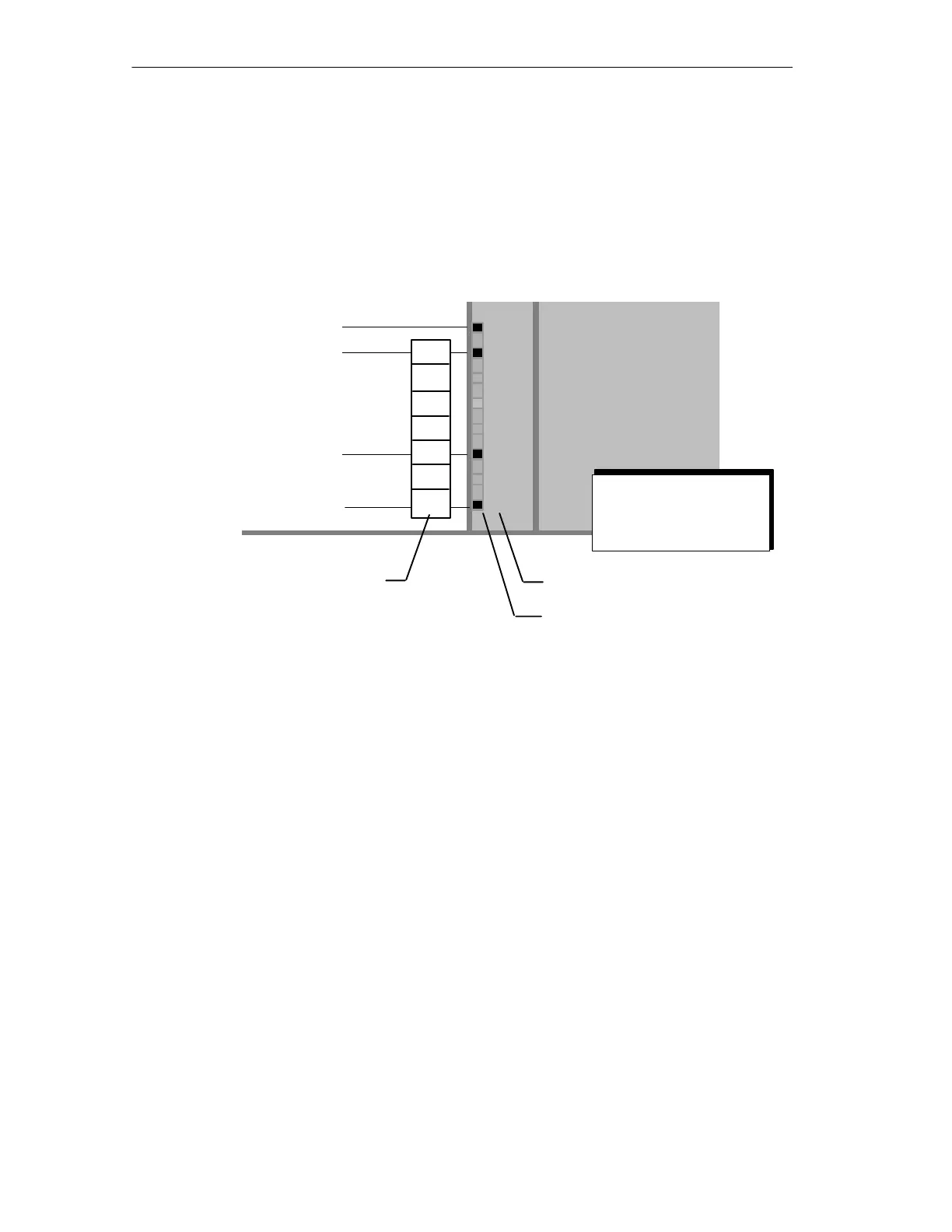
RUN
APF
CER
AUP
CM
BF
SF
ADR
Labeling field
status display
LED row
Value of the address bits
red
green
green
green
64
32
16
8
4
2
1
In the example,
the LEDs indicate the
PROFIBUS address:
64 + 4 + 1 = 69
Figure 1-5
In the example above, the PROFIBUS address 69 was set with the SET/DISPLAY
buttons.
The highest address that can be set is address 126. Remember that address 126
is reserved on PROFIBUS for special functions (address assignment). For data
exchange with a DP master, you can use addresses 1 to 125.