Data Exchange Between the DP Master and AS-i Slave
51
DP/AS-Interface Link 20E
Release 11/2002
C79000-G8976-C138–04
Example of a Configuration
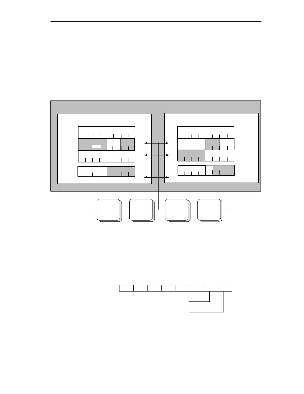
Figure 2-2 shows an example of the PROFIBUS DP master addressing four AS-i
slaves. In the DP master, the start addresses m = 0 are used for the I/O data.
The bits relevant for the user program (existing AS-i slaves) are shown on a gray
background. The bits shown on a white background are irrelevant for the user
program since no AS-i slaves are assigned here.
DP master
32
Input bytes
0
4
56
7
0
1
234
567
1
.
.
.
31
.
.
.
4 I module
Slave no. 2 Slave no. 3 Slave no. 4
Slave no. 31B
AS-i slaves
4 I module 4 I/3 O module2 I/2 O module 4 O module
2
31
0
0
1
2
slave 1
slave 1
slave 2 slave 3
Slave 30B
slave 4
slave 5
slave 2 slave 3
slave 4
slave 5
Slave 30B
Slave 31B
Bit 0
Bit 1Bit 2
Bit 3
Bit 0
Bit 0
Bit 0
Bit 0
Bit 0
Bit 0
Bit 0 Bit 0
Bit 0
Bit 0
Bit 0
Bit 0
Bit 1
Bit 1
Bit 1
Bit 1
Bit 1
Bit 1
Bit 1
Bit 1
Bit 1
Bit 1
Bit 1
Bit 1
Bit 3
Bit 2
Bit 2Bit 2
Bit 2
Bit 2
Bit 2
Bit 2
Bit 2
Bit 2
Bit 2
Bit 2
Bit 2
Bit 2
Bit 3
Bit 3
Bit 3
Bit 3
Bit 3
Bit 3
Bit 2
Bit 3
Bit 3
Bit 3
Bit 3
Bit 3
Bit 3
Bit 3 Bit 1 Bit 0
Bit 1
Bit 0
Output bytes
32
Bit 2
Slave 31B
Bit 0
Bit 1
Bit 3
Figure 2-2
In the figure above, for example, the 2I/2O module (AS-i slave number 3 with two
inputs and two outputs) occupies bits 0 and 1 in input byte 1 and bits 2 and 3 in
output byte 1.
The assignment of the AS-i terminals of the AS-i bus modules to the data bits of
the input/output bytes is shown below based on the example of slave number 3:
1 0 Bit no.
Input byte 1
Terminal 1 on the AS-i bus
module
Terminal 2 on the AS-i bus
module