LEDs, connectors, buttons
2.1 LED displays of the LINK
IE/PB LINK PN IO
Operating Instructions, 11/2017, C79000-G8976-C393-02
23
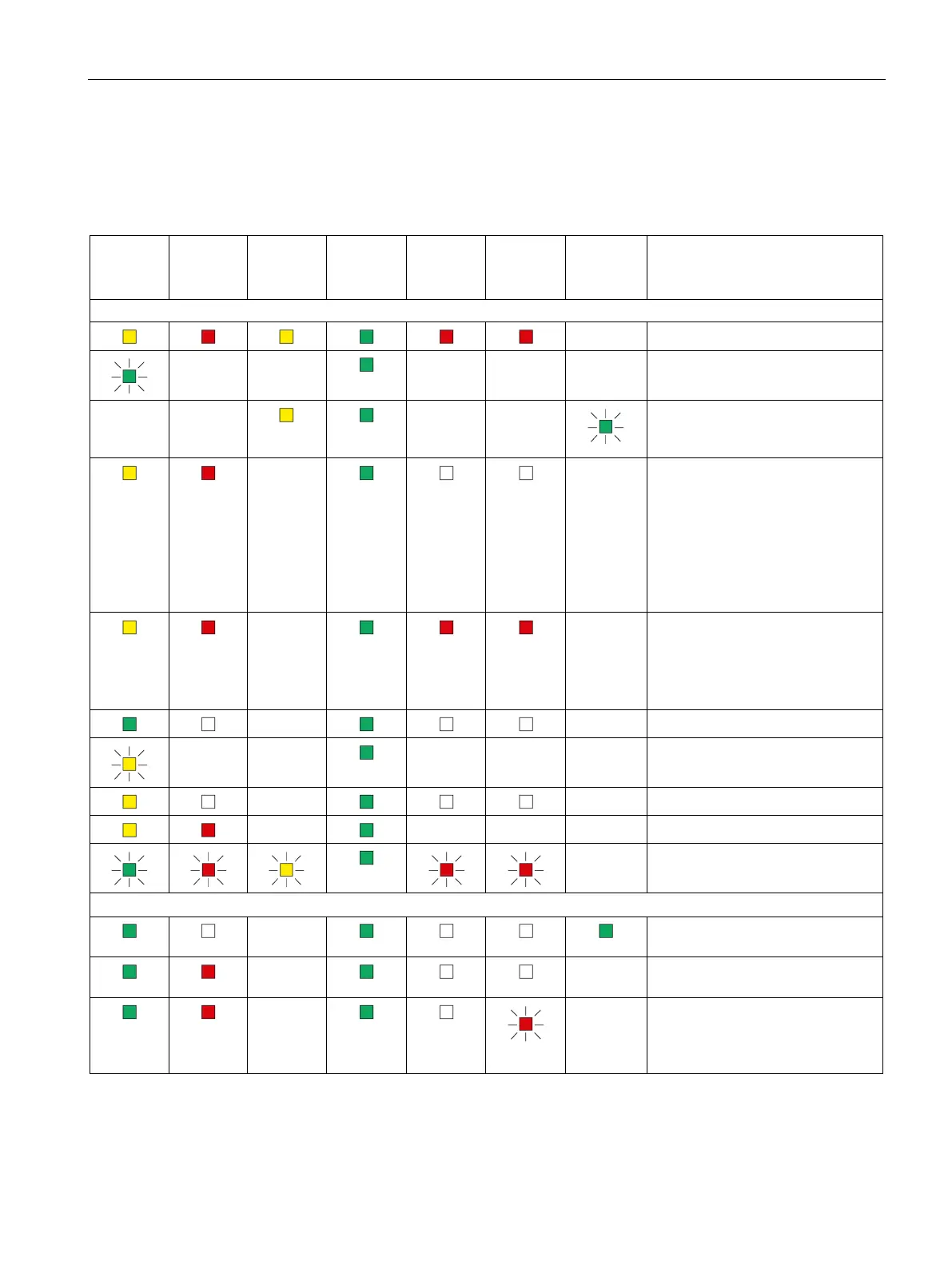
The LEDs indicate the operating and communications status of the module according to the
following scheme:
Table 2- 5 Display schemes for detailed module statuses
(yellow /
(red)
(yellow)
(green)
(red)
(red)
(green)
Startup, operating statuses, errors
- Turn on (lamp test)
- -
- - - Starting up (STOP → RUN)
- -
- -
Finding modules on Ethernet
(LK1/LK2 flashes slowly, only dur-
-
-
• Distribution of the PROFINET
configuration data during
startup
• Bus adapter configured but not
plugged in.
• Bus adapter plugged in but not
configured.
-
-
• Reset to factory settings
• Status following a memory
reset
• Device new and started up
-
- Running (RUN) without error
- -
- - - Stopping (RUN → STOP)
-
- Stopped (STOP)
-
- - - Stopped (STOP) with error
- Module fault / system error
Operating statuses, error (PROFIBUS and Ethernet)
-
Running (RUN), Ethernet connec-
tion at port, no data traffic
-
- Running (RUN), problem with a
-
- Running (RUN), module missing
on PROFIBUS or is incorrectly
configured (does not apply to
PROFINET IO).
 Loading...