150/278
Siemens Building Technologies Basic Documentation LMV51... CC1P7550en
HVAC Products 8 Commissioning instructions for the LMV5... system 01.10.2003
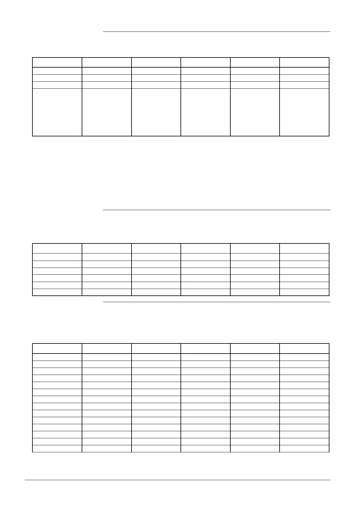
Menu level 1 Menu level 2 Menu level 3 Menu level 4 Menu level 5 Menu level 6
Params & Display
Actuators
DirectionRot
DeleteCurves
1. AirActuator
2. GasActuat.(Oil)
3. OilActuator
4. AuxActuator
5. AuxActuator 2
6. AuxActuator 3
Select the direction of rotation with Standard or Reversed.
The standard direction of rotation is anticlockwise when facing the end of the drive shaft
( → «Display and operating unit AZL5…»).
Note: To check the direction of rotation, every actuator can be rotated when in the
home position (see item 11). After setting the ignition positions / curves, the
direction of rotation can only be changed after canceling the curves and the
ignition positions on the setting menu «DeleteCurves».
Depending on the application and the type of fuel (with or without auxiliary actuator),
the auxiliary actuator can be activated or deactivated, or used as a VSD (only
LMV51.2...).
Menu level 1 Menu level 2 Menu level 3 Menu level 4 Menu level 5 Menu level 6
Params & Display
RatioControl
GasSettings
Actuator
OilSettings
Actuator
In accordance with the application and the type of fuel, the actuators can be activated
or deactivated. Here, it is also defined whether the relevant actuator influences the air
volume.
Menu level 1 Menu level 2 Menu level 3 Menu level 4 Menu level 5 Menu level 6
Params & Display
RatioControl
GasSettings
AirActuator
AuxActuator 1
AuxActuator 2
AuxActuator 3
VSD
OilSettings
AirActuator
AuxActuator 1
AuxActuator 2
AuxActuator 3
VSD
6. Selecting the
actuator’s direction of
rotation
7. LMV51...
Activating and
deactivating the actuator
LMV52...
activating and
deactivating the
actuators

 Loading...

