33/278
Siemens Building Technologies Basic Documentation LMV51... CC1P7550en
HVAC Products 4 Burner control 01.10.2003
4 Burner control
4.1 Description of inputs and outputs
This chapter describes the basic characteristics of the burner control’s inputs and
outputs. For the valuation of the inputs and activation of the outputs, refer to the
«Sequence diagrams».
The following connection facilities are provided:
• QRI... (infrared flame detector) for continuous or intermittent operation
• Ionization probe for continuous or intermittent operation
• QRB... flame detector for intermittent operation only
When using the QRB..., continuous operation is not possible!
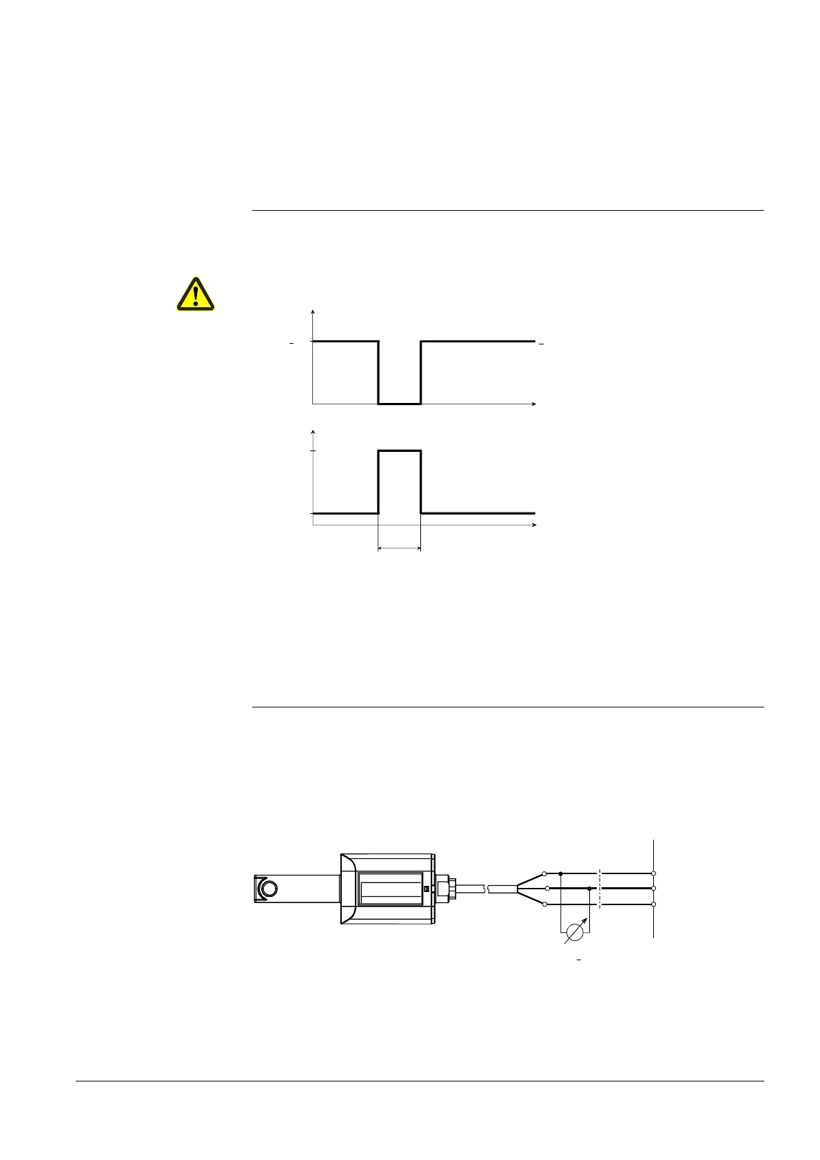
< 100 %
t
5 V
21 V
t
Test time
7550d20E/050 2
Signal
voltage
Self-test
voltage
Operating
voltage
14 V
400-600 ms
<
The self-test function of the QRI... is triggered by increasing the supply voltage to the
level of self-test voltage.
During the following test time, the signal voltage at the output of the QRI... changes to
zero so that the LMV5… will receive the anticipated flame OFF signal as a reply to the
test.
If the behavior is correct, operation is continued until the next test cycle is reached.
The test cycle is dependent on the parameterization of the LMV5... .
Note: All measured voltages refer to connection terminal N (X10–02, terminal 4).
Supply voltage operation / test at terminal POWER QRI...
(X10–02, terminal 2) approx. DC 14 / 21 V
Minimum signal voltage required at terminal FSV / QRI...
(X10–02, terminal 6) DC 3.5 V
display flame approx. 50 %
7719a01E/0502
SIEMENS
QRI
Made in Germany
Landis & Staefa
blue
brown
0...10 V
Ri
> 10 M
Ω
X10-02 / 6
X10-02 / 4
X10-02 / 2
LMV...
+
black
For detailed information, refer to Data Sheet 7719.
Flame signal input and
flame detector
X10–01 and X10–03
Self-test function
LMV5... / QRI...
Technical data
flame supervision
QRI (suited for
continuous operation)
Connection diagram

 Loading...

