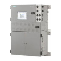
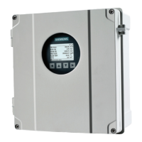
Figure 2-47 TIB Color Touchscreen Door Exploded View
9. Remove the TIB protective cover by removing the 4 screws. (A in exploded view) This
allows access to two of the 6 mounting studs for the LCD assembly. (E in exploded view)
10.Disconnect the three connectors of the display cable assembly; the backlight connector,
the TIB cable connector, and the LCD connector. (B in exploded view)
Electronic Compartment Component Descriptions and Maintenance Procedures
2.10 Color Touchscreen
Maxum II Reference Manual
Manual, 7/2017, 2000596-001 89

 Loading...


