Issue 03/01 10 Engineering Information
MICROMASTER 411 & COMBIMASTER 411 Operating Instructions
6SE6400-5CA00-0BP0
151
Quick Guide to setting up PROFIBUS
The bus cable between the master device and the drive must be connected
correctly. this includes the necessary termination resistors.
Bus Termination within the PROFIBUS module can be achieved using the
termination switch (SW1).
The bus cable must be screened and the screen must be connected to the
housing of the cable connector.
The PROFIBUS master must be configured correctly so that communications
can be realized with a DP slave using PPO type 1 or PPO type 3 (only PPO
type 1, if the PPO type cannot be configured via remote operator control).
Installation should be in conformance with EMC directives and regulations (this is
described in detail in the operating manuals for the drive and the PLC).
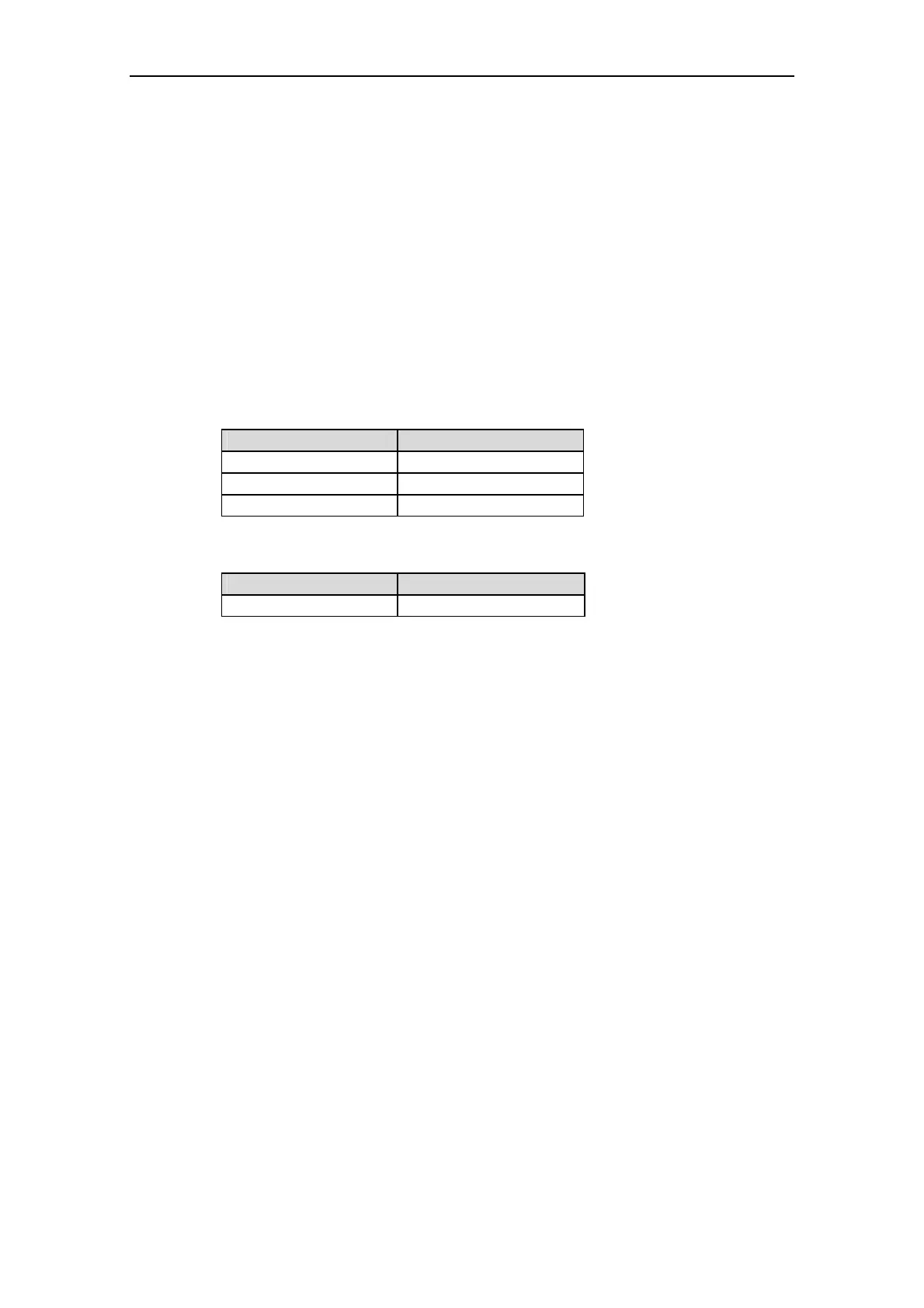
Table 10-10 Technical data – 411 PROFIBUS Module
Item Description
Dimensions H x W x D 107,8 mm x 128 mm x 40,5 mm
Degree of protection IP66
Maximum bus speed 12 MBaud
Table 10-11 PROFIBUS Ordering information
Designation Order No.
PROFIBUS module 6SE6401-1PB00-0AA00

 Loading...


