Issue 03/01 3 Commissioning
MICROMASTER 411 & COMBIMASTER 411 Operating Instructions
6SE6400-5CA00-0BP0
43
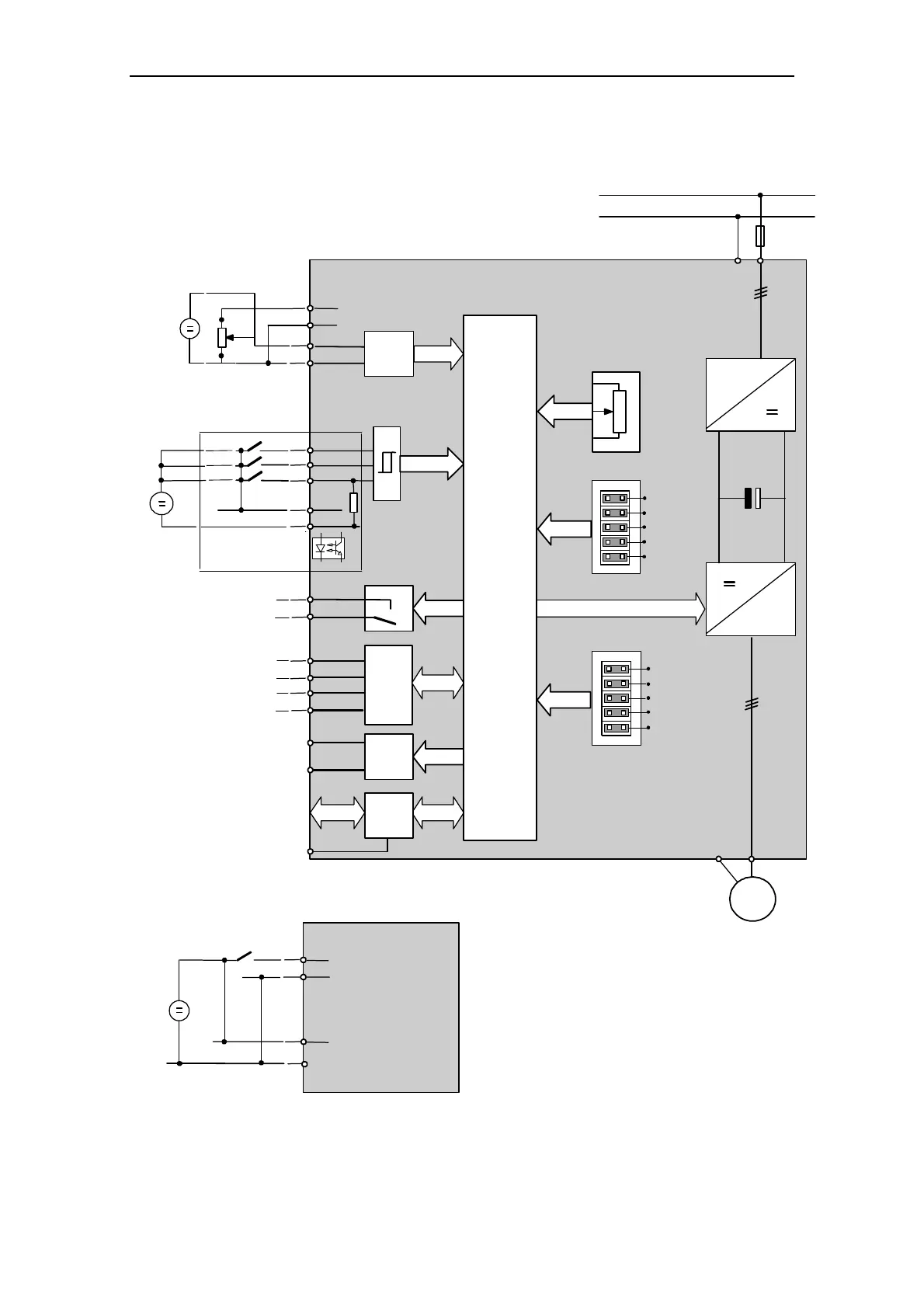
3.1 Block Diagram
1
2
3
–
+
24 V
DIN1
DIN2
DIN3
4
5
RL
RLB
RLC
COM 1
COM 2
Tx+
0 V
A/D
AIN +
AIN -
4
5
7
6
CPU
~
~
3
M
PE
3 AC 380 V-480 V
FS1
L1, L2,L3
PE
≥
4.7 k
Ω
24 V
0 V
PE
COM 4
COM 3
Rx
+6.5 V
5
24 V max
–
+
7
6
DIN4
4
8
9
1 Sec
2 Sec
5 Sec
x 10
x 20
CPU
SOL
(TTL)
Analogue Input source
Input Voltage: 0 to +10 V / 24 V
(on 500 Ohm resistor)
External
Power supply
Output Relais (RL) Contacts
250 V AC, 2 A max.
30 V DC, 5 A max.
+24 V(100 mA max)
0 V (isolated)
EM Brake
Option
Comm.
Options
(Shield)
Serial
Interface
RS232
Brake
Interface
The Analogue input circuit can be configured ,
to provide an additional digital input (DIN4) as shown
Switching voltage must b
+24 V(100 mA max)
?????? V or 0 V (isolated)
Control jumper
Pot = Run
24 V AIN
DC Brake
Fan/Pump M~n2
60 Hz
Ramp time
Jumpers
Motor Potentiometer
Figure 3-1 COMBIMASTER 411 & MICROMASTER 411 Block Diagram

 Loading...


