6 Troubleshooting Issue 03/01
MICROMASTER 411 & COMBIMASTER 411 Operating Instructions
80
6SE6400-5CA00-0BP0
WARNING
Repairs on equipment may only be carried out by Siemens Service, by repair
centers authorized by Siemens or by qualified personnel who are thoroughly
acquainted with all the warnings and operating procedures contained in this
manual.
Any defective parts or components must be replaced using parts contained in
the relevant spare parts list.
Disconnect the power supply before opening the equipment for access.
6.1 Troubleshooting with the Inverter LED
Check the status of the LED located within the control potentiometer.
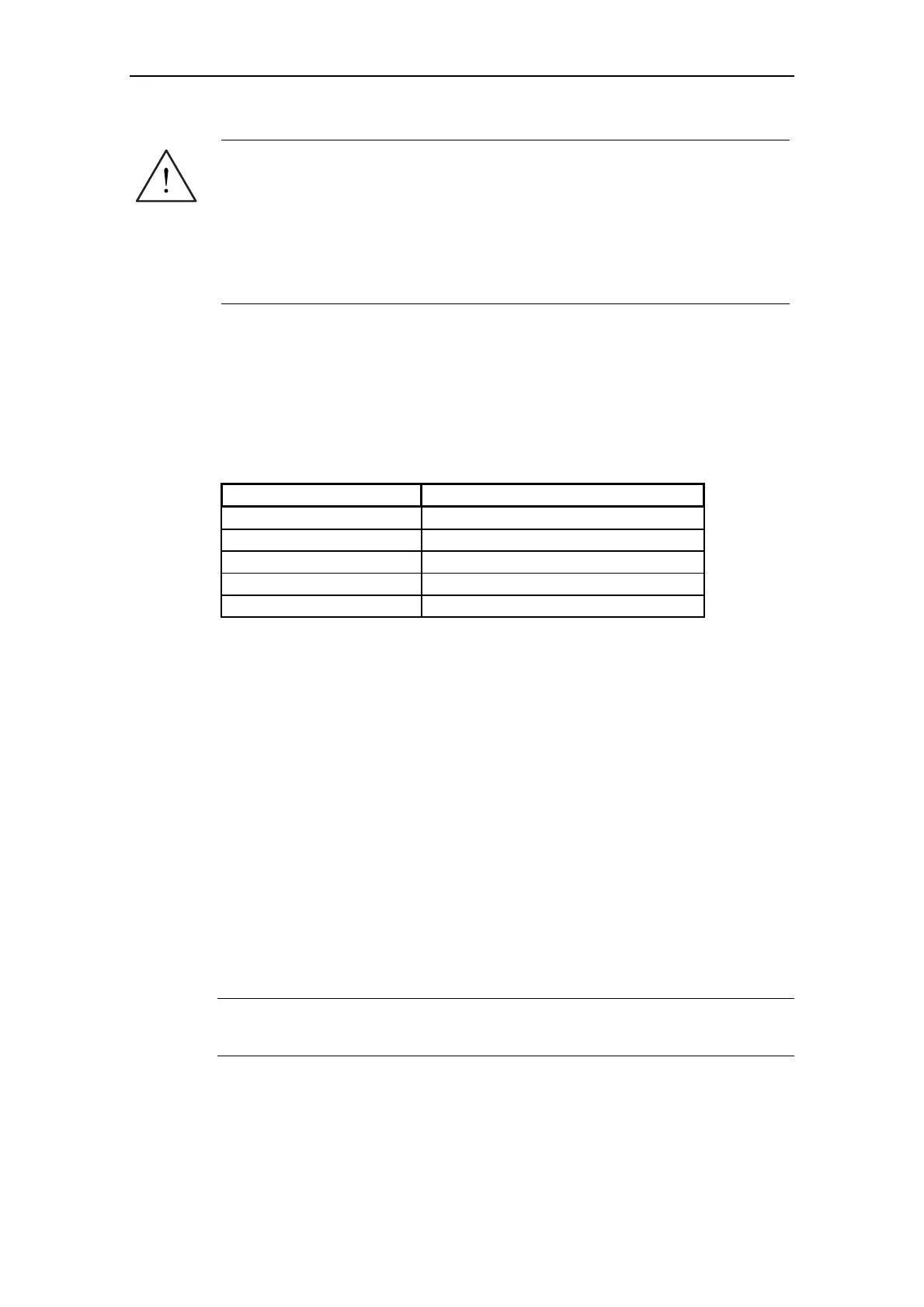
A list of the LED status indications are given in Table 6-1.
Table 6-1 Inverter LED Indication
Condition Status
200 ms on / 800 ms off Power On / Ready
Continuous on Running
800 ms on / 200 ms off Warning (general)
500 ms on / 500 ms off Trip (general)
OFF Off/Mains supply fault / No inverter power
6.2 Troubleshooting with the Basic Operator Panel
Warnings and faults are displayed on the BOP with Axxx and Fxxx respectively.
If the motor fails to start when the ON command has been given:
Check that P0010 = 0.
Check that a valid ON signal is present.
Check that P0700 = 2 (for Terminal I/O control) or
P0700 = 1 (for BOP control).
Check that the setpoint is present (0 to 10 V on Terminal 7) or the setpoint has
been entered into the correct parameter, depending upon the setpoint source
(P1000). For further details see the Parameter List.
If the motor fails to run after changing the parameters, set P0010 = 30 then P0970
= 1 and press P to reset the inverter to the factory default parameter values.
By using a switch between terminals 1 and 4 on the I/O board, the drive should
now run to the defined setpoint (established by analog input and/or control
potentiometer).
NOTICE
For the MICROMASTER 411 the motor data must relate to the inverter data power
range and voltage.

 Loading...


