Data interfaces
36
Siemens Building Technologies
Fire Safety & Security Products 07.2008
13.3.3 Data format
There are three aspects to the format of the data message, all of which can be var-
ied, depending on the interface number you use:
z Framing bits at the start and finish of the message.
z Any parity bits which may be used.
z The data from the card.
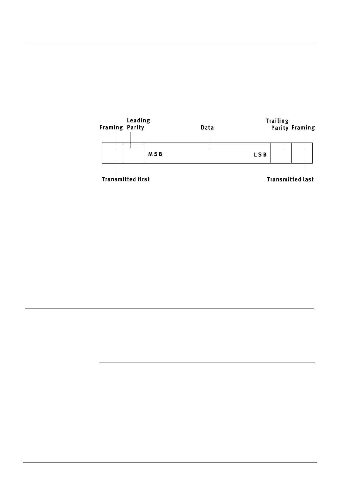
The following diagram shows a typical message structure.
Framing bits are usually either not used or confined to start and stop bits which
have a fixed state.
Parity bits are used to check the integrity of the data message. Parity may be odd
or even and it may be calculated from the data only or from the data and some
framing bits. The Reader can calculate the leading parity bit based on the first 13
bits of 26-bit Wiegand format if you require, see chapter
12.4.5 pxxx (calculation of
leading parity bit for 26-bit Wiegand interfaces).
Card data
Data from the card can be any number of bits up to a maximum of 48. This in-
cludes any parity check bits which may be stored in the card code. The interface
selected also determines whether the data is sent most significant bit first or least
significant bit first.
13.3.4 Interface settings
All other options to do with the Wiegand interface such as variation of pulse width
and interval are selected using the interface number programmed into the configu-
ration card (see chapter
12.3 The configuration card). The following table shows
some typical timing for a Wiegand interface:
Interface Number Function
02 Lower 32 bits of data msb first, 100µs pulse, 400µs space
04 Start bit 1, lower 32 bits of data lsb first, stop bit 0, 50µs pulse, 2ms space
0E Lower 25 bits of data msb first, trailing parity bit, 50µs pulse, 450µs space
12 Leading parity bit (if configured), lower 24 bits of data msb first, trailing parity
bit, 50µs pulse, 3ms space (use for “standard” 26-bit Wiegand).
24 Data bit 32, four zeros, lower 31 bits of data msb first, 50µs pulse, 1.2ms
59 4101/4010 Controller interface - use when connecting to 4422 swipe module
or 4010 swipe Controller - set 4101/4010 Controller to interface 303.
8E Card-determined variable length data output (see below)