Data interfaces
38
Siemens Building Technologies
Fire Safety & Security Products 07.2008
13.4 Magnetic Stripe
A Magnetic Stripe interface is provided which simulates the output of a magnetic
card reader.
13.4.1 Connections
The pin connections for the Magnetic Stripe interface are as follows:
0V Ground
D0 Data
D1 Strobe
DA Present
13.4.2 Electrical characteristics
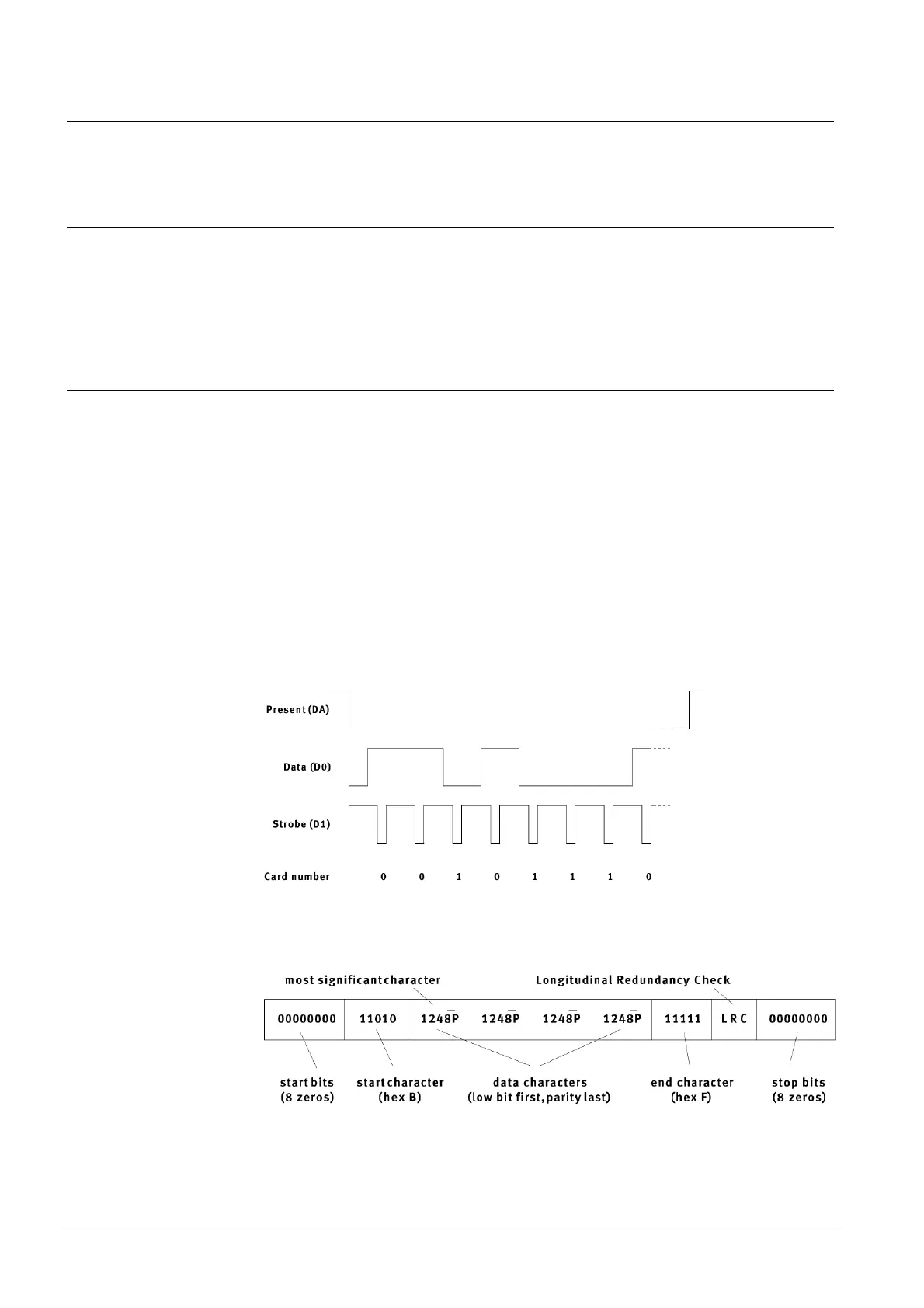
The interface provides three outputs: Present, Data and Strobe.
Present is a signal given by a magnetic card reader indicating that a card has
been inserted in the slot. On the Proximity Readers, this signal becomes active just
before data is sent and is released after the data has been sent. The polarity of the
signal is active-low.
Data is a signal whose level reflects the value of the bit in the code. The polarity of
the signal is “inverse logic”, which means a high signal indicates a zero and a low
signal indicates a one.
Strobe is a series of clock pulses. The polarity of the signal is active-low. Data can
be sampled on either the rising edge or the falling edge of the Strobe signal.
The following diagram should make clear the action of all three signals in a data
transfer:
The following diagram shows the format of the Magnetic Stripe output:
This example shows an output of 4 data characters only - all of the MagneticStripe
interfaces which are available on the Proximity Readers output 10 or 11 data char-
acters as shown below.