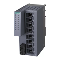
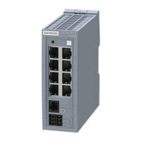
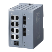
Description of the device
2.2 The LEDs
SCALANCE X-200
20 Operating Instructions, 03/2015, C79000-G8976-C284-06
Port LEDs "P" (green/yellow LEDs)
The LEDs of the Ethernet connectors can be lit green or yellow. The meanings of the display
are as follows:
Link exists, no data reception
Yellow Lit Link exists, data being received
Device startup. The LED lights up for approximately 6 seconds.
Setting or display of the fault mask
The following statuses of the port LEDs do not exist on devices with the IRT function:
Link exists and port in "blocking" status.
In this status, the port only receives management data (no user data).
Green flashes
three times per
Link exists and port is deactivated by the management.
In this status, no data is sent or received via the port.
Green flashes
four times per
Port exists and is in the "monitor port" status.
In this status, the data traffic of another port is mirrored to this port.
Diagnostics LEDs for optical connectors "F" (yellow LED)
You will find the diagnostics LEDs only on the devices with the IRT function.
The status of the optical connectors is indicated by an additional yellow LED per connector.
The LEDs signal the following statuses:
Yellow Lit Check the plug-in connection and the quality of the fiber-optic cable. If necessary,
- Off Relevant only if the link exists. The existing link power margin is adequate for error-
Show Location
Localizing an IE Switches X-200
To identify an IE Switch X-200 locally and with certainty, you can use the "show location"
function on a programming device to select the node over the network and make it flash.
This can be used, for example, when assigning addresses to make sure that the correct
node receives the address. All port LEDs of the addressed node flash green at 2 Hz.
With the Primary Setup Tool (PST) V3.0 or higher, you can trigger this function with "Module
\ Flash".
 Loading...