Connecting up
5.2 Power supply
SCALANCE X-200
Operating Instructions, 03/2015, C79000-G8976-C284-06
47
Power supply looped through
The devices also have a connector for the switched mode and unswitched power supply of
other devices with 24 VDC. Via these interfaces (L1+, N1 and L2+, N2) it is possible to loop
the power through with connector technology compliant with PROFINET.
Note
Notes on operating under marginal conditions
When looping through the power supply, take into account the limit values; in other words,
the maximum permitted current depending on the ambient temperature; refer to the table
"Operation under marginal conditions" below.
When looping through the power su
pply under the marginal conditions described below, the
device may only be operated if it is installed horizontally. Horizontal installation position
means that the device is mounted, for example on a horizontal DIN or standard rail or that
the labeling on
the device can be read in the normal reading direction.
If no power is looped through, any installation position is permitted.
Table 5- 1 Operation under marginal conditions
SCALANCE X204IRT PRO only:
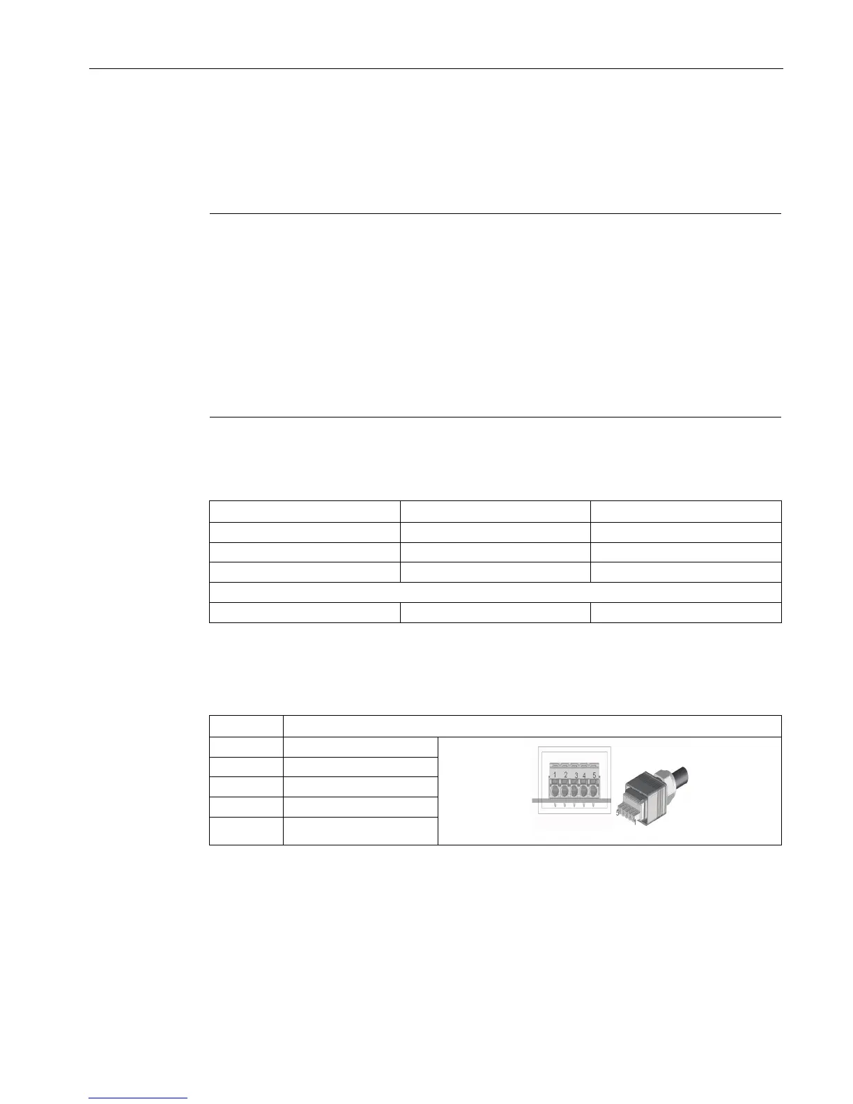
Pin assignment of the connectors
The following table shows the pin assignment of the two power supply connectors:
 Loading...