A-14
C7-613 Control System
A5E00138934-03
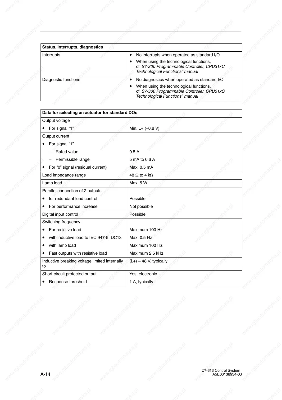
Status, interrupts, diagnostics
Interrupts • No interrupts when operated as standard I/O
• When using the technological functions,
cf. S7-300 Programmable Controller, CPU31xC
Technological Functions” manual
Diagnostic functions • No diagnostics when operated as standard I/O
• When using the technological functions,
cf. S7-300 Programmable Controller, CPU31xC
Technological Functions” manual
Data for selecting an actuator for standard DOs
Output voltage
• For signal “1” Min. L+ (–0.8 V)
Output current
• For signal “1”
– Rated value 0.5 A
– Permissible range 5 mA to 0.6 A
• For “0” signal (residual current) Max. 0.5 mA
Load impedance range 48 Ω to 4 kΩ
Lamp load Max. 5 W
Parallel connection of 2 outputs
• for redundant load control Possible
• For performance increase Not possible
Digital input control Possible
Switching frequency
• For resistive load Maximum 100 Hz
• with inductive load to IEC 947-5, DC13 Max. 0.5 Hz
• with lamp load Maximum 100 Hz
• Fast outputs with resistive load Maximum 2.5 kHz
Inductive breaking voltage limited internally
to
(L+) – 48 V, typically
Short-circuit protected output Yes, electronic
• Response threshold 1 A, typically