Installing and Wiring the C7-613
2-10
C7-613 Control System
A5E00138934-03
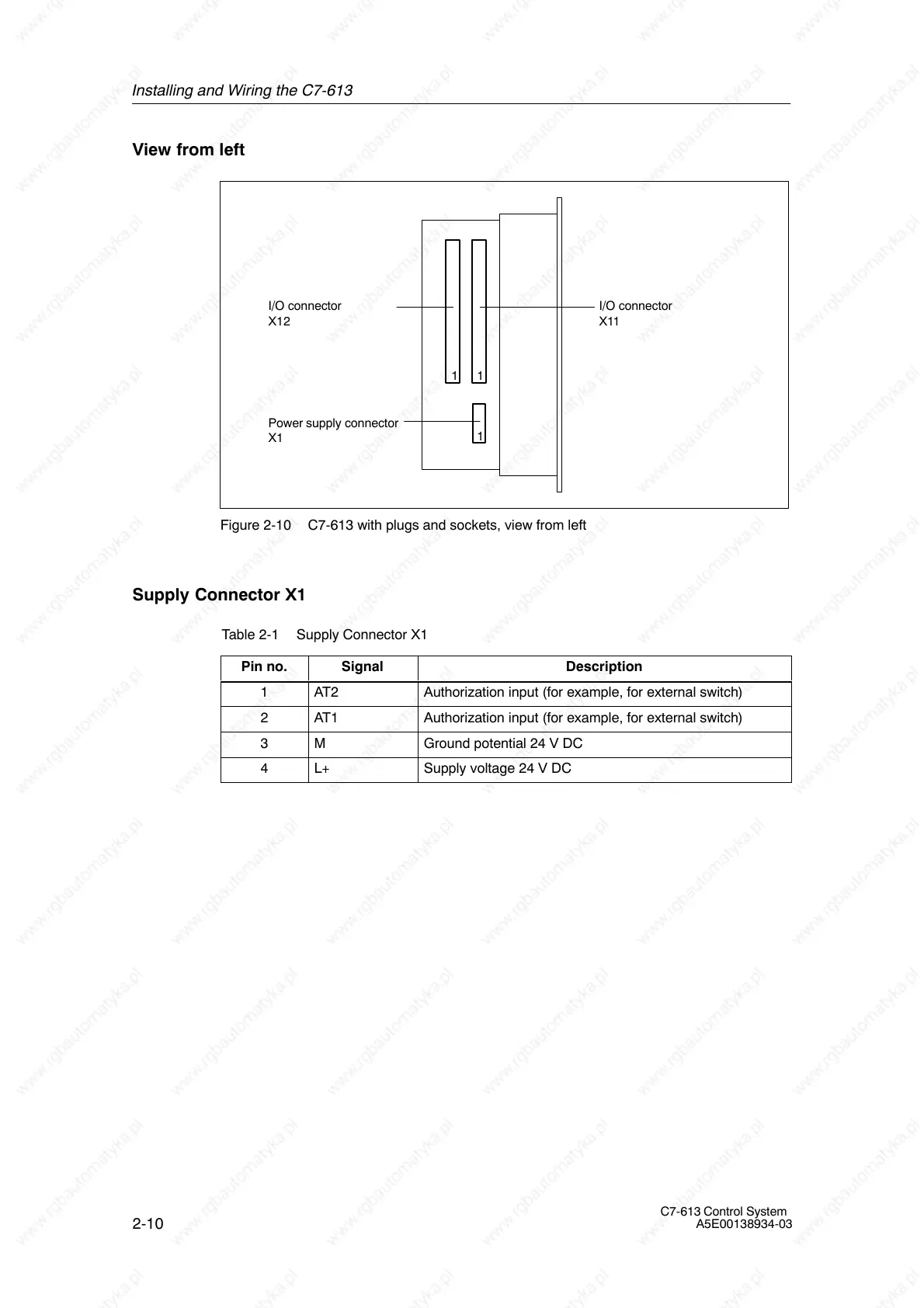
View from left
Power supply connector
X1
I/O connector
X12
I/O connector
X11
1
11
Figure 2-10 C7-613 with plugs and sockets, view from left
Supply Connector X1
Table 2-1 Supply Connector X1
Pin no.
Signal Description
1 AT2 Authorization input (for example, for external switch)
2 AT1 Authorization input (for example, for external switch)
3 M Ground potential 24 V DC
4 L+ Supply voltage 24 V DC