Installing and Wiring the C7-613
2-13
C7-613 Control System
A5E00138934-03
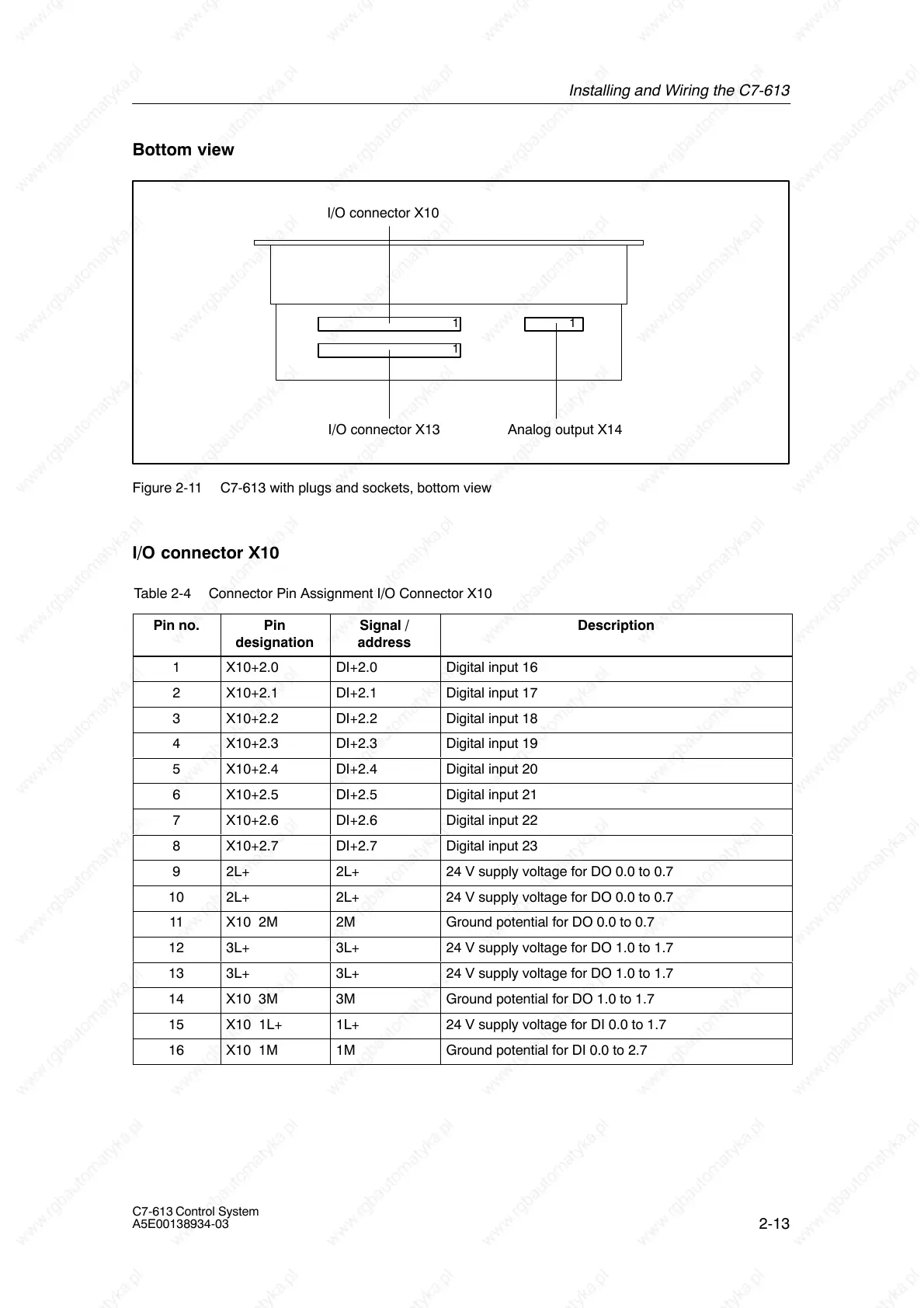
Bottom view
Analog output X14I/O connector X13
I/O connector X10
1
1
1
Figure 2-11 C7-613 with plugs and sockets, bottom view
I/O connector X10
Table 2-4 Connector Pin Assignment I/O Connector X10
Pin no.
Pin
designation
Signal /
address
Description
1 X10+2.0 DI+2.0 Digital input 16
2 X10+2.1 DI+2.1 Digital input 17
3 X10+2.2 DI+2.2 Digital input 18
4 X10+2.3 DI+2.3 Digital input 19
5 X10+2.4 DI+2.4 Digital input 20
6 X10+2.5 DI+2.5 Digital input 21
7 X10+2.6 DI+2.6 Digital input 22
8 X10+2.7 DI+2.7 Digital input 23
9 2L+ 2L+ 24 V supply voltage for DO 0.0 to 0.7
10 2L+ 2L+ 24 V supply voltage for DO 0.0 to 0.7
11 X10 2M 2M Ground potential for DO 0.0 to 0.7
12 3L+ 3L+ 24 V supply voltage for DO 1.0 to 1.7
13 3L+ 3L+ 24 V supply voltage for DO 1.0 to 1.7
14 X10 3M 3M Ground potential for DO 1.0 to 1.7
15 X10 1L+ 1L+ 24 V supply voltage for DI 0.0 to 1.7
16 X10 1M 1M Ground potential for DI 0.0 to 2.7