Installing and Wiring the C7-613
2-14
C7-613 Control System
A5E00138934-03
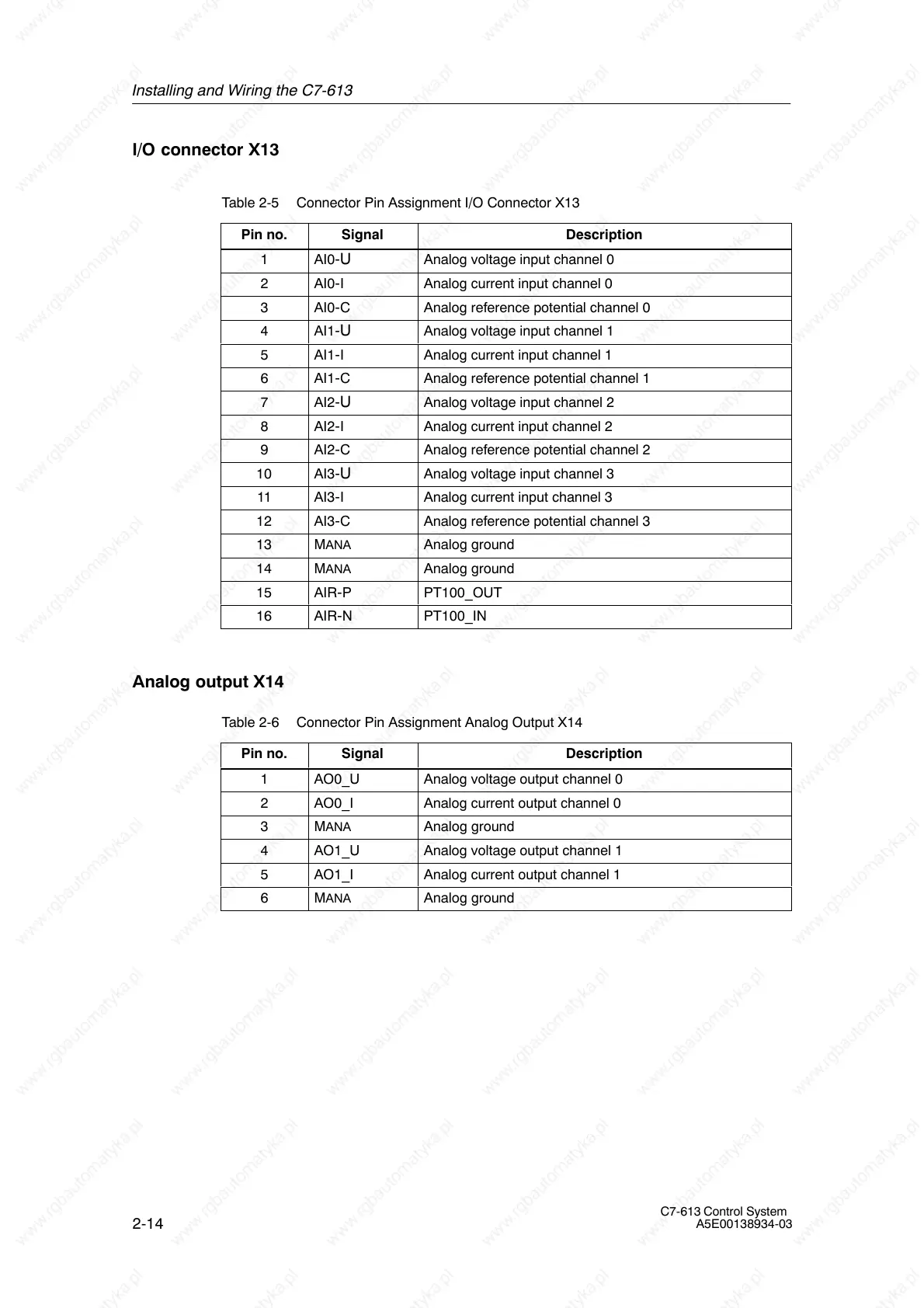
I/O connector X13
Table 2-5 Connector Pin Assignment I/O Connector X13
Pin no.
Signal Description
1 AI0-U Analog voltage input channel 0
2 AI0-I Analog current input channel 0
3 AI0-C Analog reference potential channel 0
4 AI1-U Analog voltage input channel 1
5 AI1-I Analog current input channel 1
6 AI1-C Analog reference potential channel 1
7 AI2-U Analog voltage input channel 2
8 AI2-I Analog current input channel 2
9 AI2-C Analog reference potential channel 2
10 AI3-U Analog voltage input channel 3
11 AI3-I Analog current input channel 3
12 AI3-C Analog reference potential channel 3
13 MANA Analog ground
14 MANA Analog ground
15 AIR-P PT100_OUT
16 AIR-N PT100_IN
Analog output X14
Table 2-6 Connector Pin Assignment Analog Output X14
Pin no.
Signal Description
1 AO0_U Analog voltage output channel 0
2 AO0_I Analog current output channel 0
3 MANA Analog ground
4 AO1_U Analog voltage output channel 1
5 AO1_I Analog current output channel 1
6 MANA Analog ground