Installing and Wiring the C7-613
2-15
C7-613 Control System
A5E00138934-03
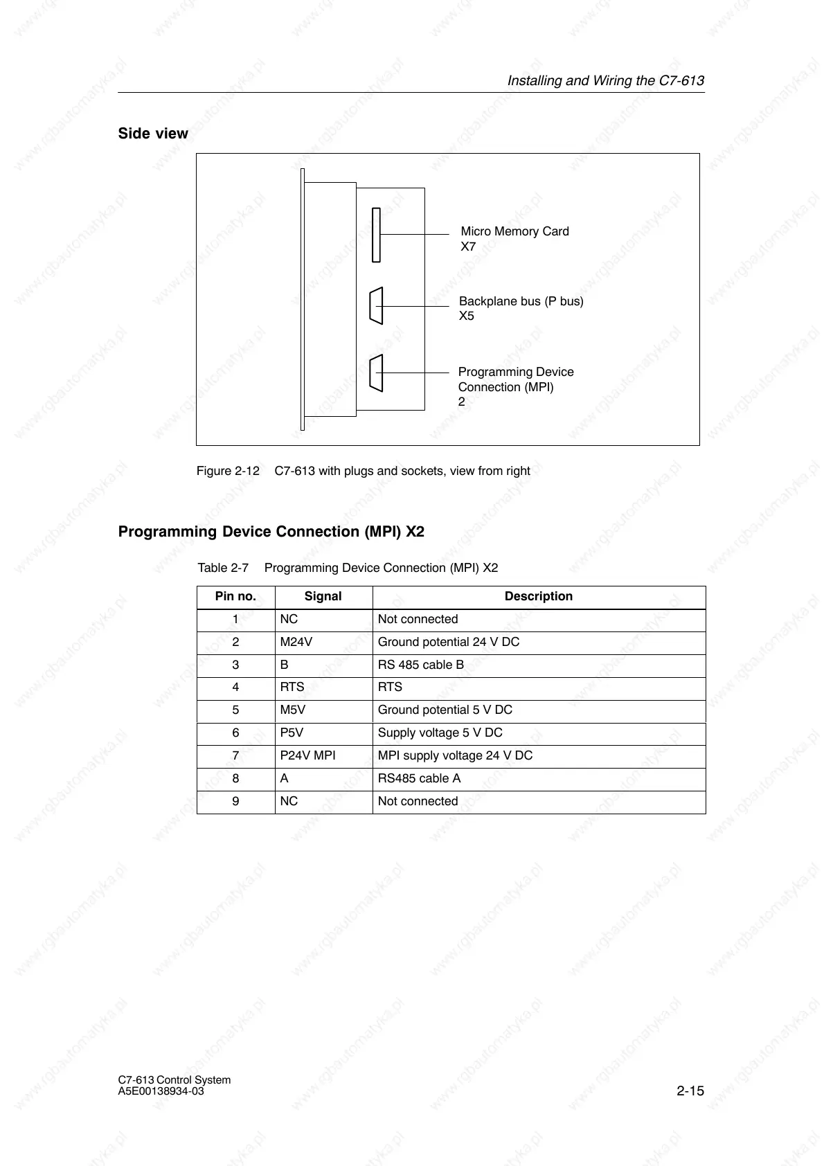
Side view
Programming Device
Connection (MPI)
2
Backplane bus (P bus)
X5
Micro Memory Card
X7
Figure 2-12 C7-613 with plugs and sockets, view from right
Programming Device Connection (MPI) X2
Table 2-7 Programming Device Connection (MPI) X2
Pin no.
Signal Description
1 NC Not connected
2 M24V Ground potential 24 V DC
3 B RS 485 cable B
4 RTS RTS
5 M5V Ground potential 5 V DC
6 P5V Supply voltage 5 V DC
7 P24V MPI MPI supply voltage 24 V DC
8 A RS485 cable A
9 NC Not connected