Wiring
7.3 Electrical configuration
CPU 1515SP PC2 (F/T/TF)
Operating Instructions, 09/2018, A5E42603425-AA
39
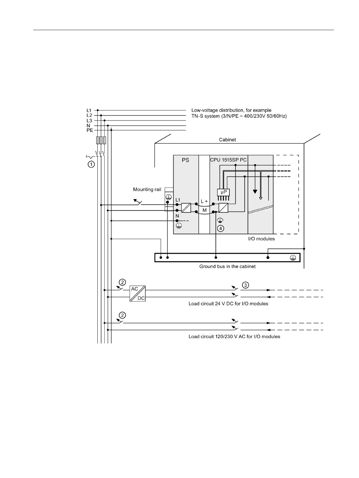
The following figure shows the overall configuration of a CPU 1515SP PC2 with power
supply from a TN-S system. The power supply supplies the CPU 1515SP PC2 and the load
circuit for the 24 V DC modules.
For the CPU 1515SP PC2, there is a fixed connection between the ground infeed terminal
and the contact springs to the mounting rail. You must ground the mounting rail separately in
the control cabinet.
Short-circuit and overload protection
Load current supply (galvanic isolation)
This connection is established automatically with the CPU 1515SP PC2.
The represented layout of the power connections does not correspond to the actual layout; it was
chosen for demonstration purposes only.
Figure 7-2 Connecting the load voltage reference potential

 Loading...


