Wiring
4.4 Connecting the motor
F-TM ServoDrive
Equipment Manual, 02/2020, A5E47579503-AA
25
4.4 Connecting the motor
Overview
F-TM ServoDrive supports permanent magnet synchronous motors (PMSM) with suitable
encoders.
Wiring the motor phases
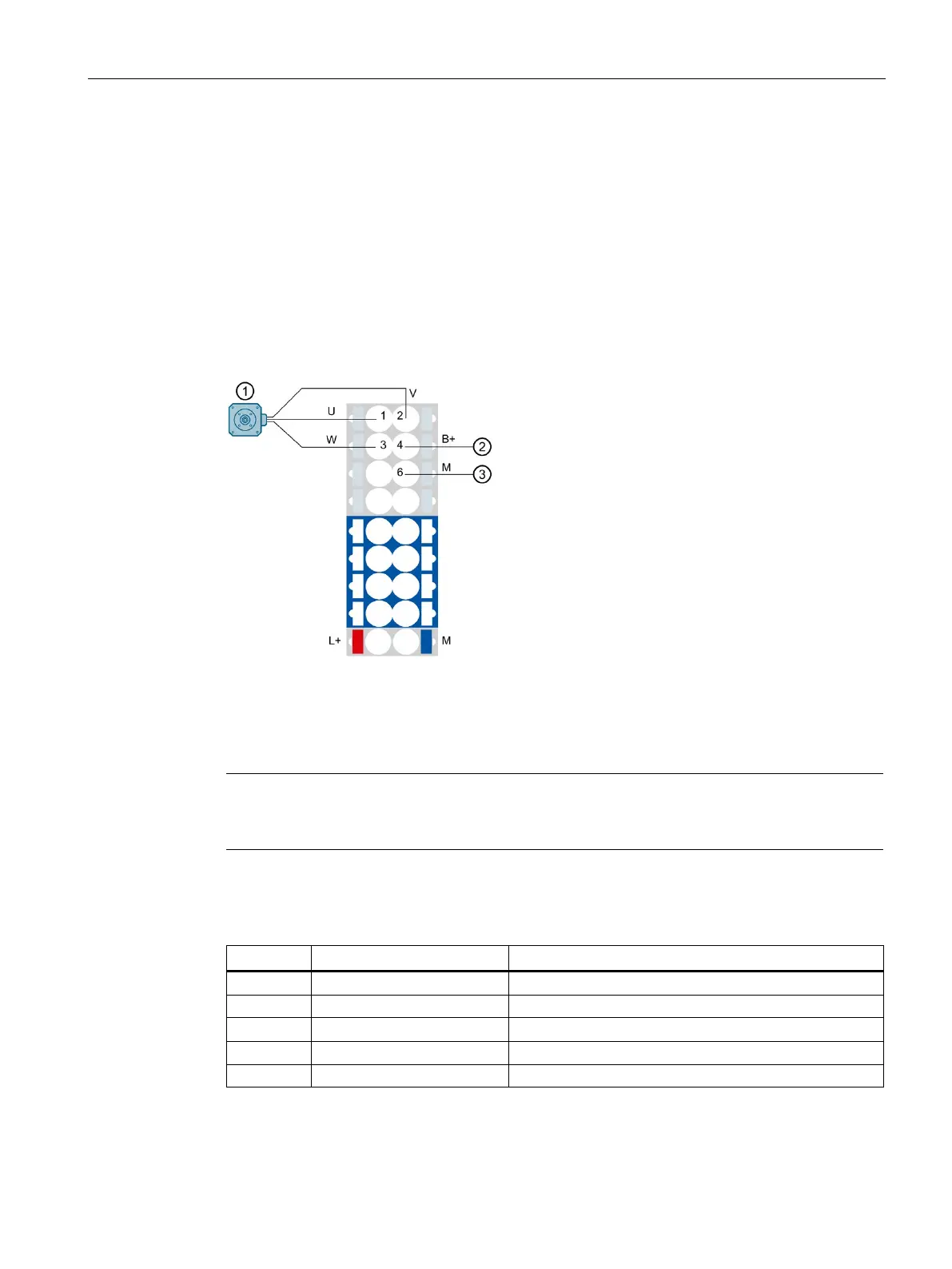
The following figure shows the connection of the motor phases to the BaseUnit:
Negative connection for brake or braking resistor
Figure 4-3 Connecting the motor
Note
In addition to the shield connection on the ET 200SP the cable shield must also
be grounded
with a suitable fastening, for example with a metal clip on the control cabinet rear panel.
Pin assignment
3 W Motor phase W
Negative connection, e.g. for braking resistor
 Loading...


