Wiring
4.6 Connecting an external braking resistor
F-TM ServoDrive
Equipment Manual, 02/2020, A5E47579503-AA
31
Wiring an external braking resistor
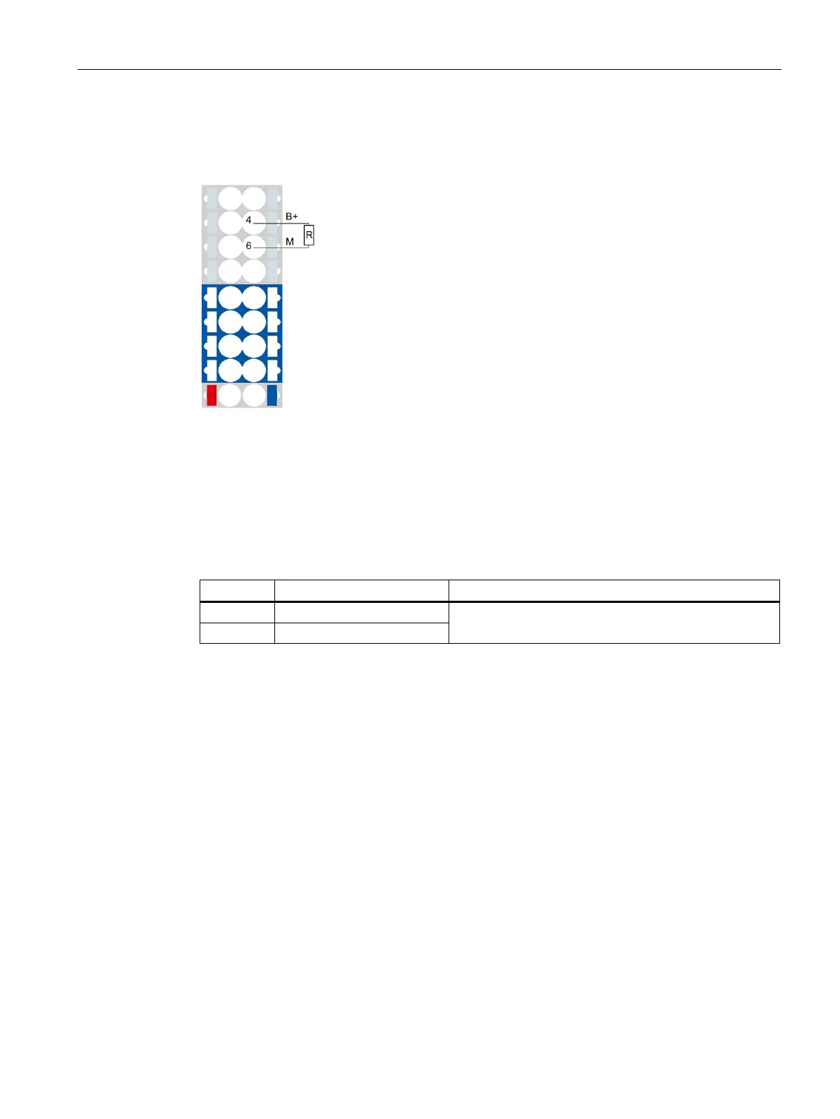
The figure below shows the connection of an external braking resistor as an example:
Positive terminal of braking resistor
Negative terminal of braking resistor
Figure 4-7 Connection of external braking resistor
Pin assignment
Table 4- 5 Pin assignment: Wiring an external braking resistor
Connection of external braking resistor
External braking resistor for potential group with several F-TM ServoDrive
If you have connected multiple F-TM ServoDrive to form a potential group, it may be
sufficient to equip only one module with an external braking resistor.

 Loading...


