Introduction
3.1 AS-Interface
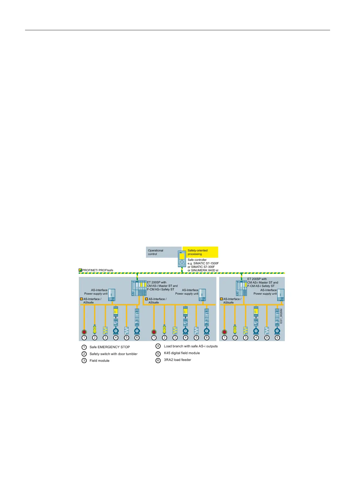
Safety engineering with AS‑Interface in the SIMATIC ET 200SP, including typical circuit diagram
12 Function Manual, 08/2020, A5E44991382002A/RS-AB/002
3.1.3 Creating an AS-Interface network
An AS-i network always comprises a master, an AS-i power supply unit, and the AS-i slaves.
AS-i is a single master system, i.e. a master module collects the data from multiple AS-i slaves
and transfers it to the process image of the PLC. From the perspective of the PLC CPU, the AS-i
master acts like an I/O module with numerous inputs and outputs.
AS-i master and AS-i slaves are connected to one another via an AS-i cable. The AS-i master
and the AS-i slaves are positioned freely on the cable.
The AS-i cable has only two wires: ASI+ and ASI−. The AS-i master and all AS-i slaves only have
to be connected to these two wires. Slaves in the IP65 version are easily connected to the AS-i
flat cable.
To supply power to the AS-i network, an AS-i power supply unit can be connected to the AS-i
cable at any position.
The AS-i power supply unit contains a data decoupling circuit that enables the AS-i
communication signals and the direct voltage to supply the modules and sensors to run on
the same AS-i cable. Parallel connection of two AS-i power supply units is not permissible.
This is in order to maintain the function of the data decoupling.
In an AS-i network with repeaters, a new segment is inserted downstream of each repeater;
each repeater requires a separate AS-i power supply unit.
The AS-Interface is designed as a single-master system with cyclic polling.
An AS-i network always contains only one master, which queries the data of all the nodes at
regular, defined intervals.
Figure 3-1 AS-Interface configuration with AS-i Master modules in the ET 200SP

 Loading...


