Circuit diagram example
4.3 Hardware and software components
Safety engineering with AS‑Interface in the SIMATIC ET 200SP, including typical circuit diagram
28 Function Manual, 08/2020, A5E44991382002A/RS-AB/002
4.3 Hardware and software components
4.3.1 Validity
This application example is valid for:
• All SIMATIC F controllers
• STEP 7 Professional as from V 15
4.3.2 Components used
The application was created with the following components.
Hardware components
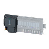
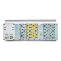
CPU 1512SP F-1 PN ET 200SP including server
module
Bus adapter 2 x RJ45 plug sockets
AS-Interface communication
module
AS-Interface safety
communication module
Fail-safe digital output
module
Light base unit 20 mm, type C0 (new load
group)
Dark base unit 20 mm, type C1 (jumpered to the
left)
Light base unit 15 mm, type A0 (new load
group)
Dark base unit 15 mm, type A0 (jumpered to
the left)
3SU AS-Interface enclosure
EMERGENCY STOP mushroom pushbutton
Illuminated pushbutton, toggle switch
With tumbler and auxiliary release
IN: 120 V ... 230 V AC, OUT: 3 A AS-i
Software components

 Loading...


